
How to Use Lolin32 ESP32: Examples, Pinouts, and Specs
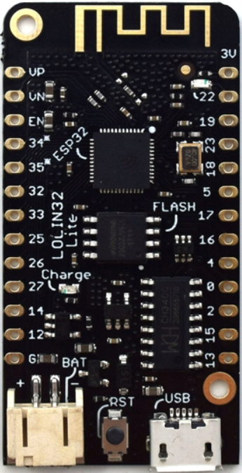
 Design with Lolin32 ESP32 in Cirkit Designer
Introduction
The Lolin32 ESP32 is a versatile development board created by WeMos, based on the Espressif ESP32 microcontroller. This board is equipped with WiFi and Bluetooth functionalities, making it a powerful platform for Internet of Things (IoT) projects and wireless applications. Its low power consumption and wide range of features make it suitable for hobbyists, educators, and professionals looking to develop connected devices.
Explore Projects Built with Lolin32 ESP32
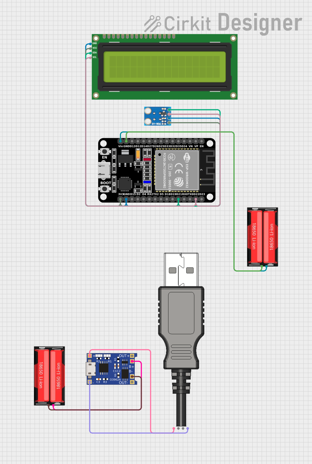
 Open Project in Cirkit Designer
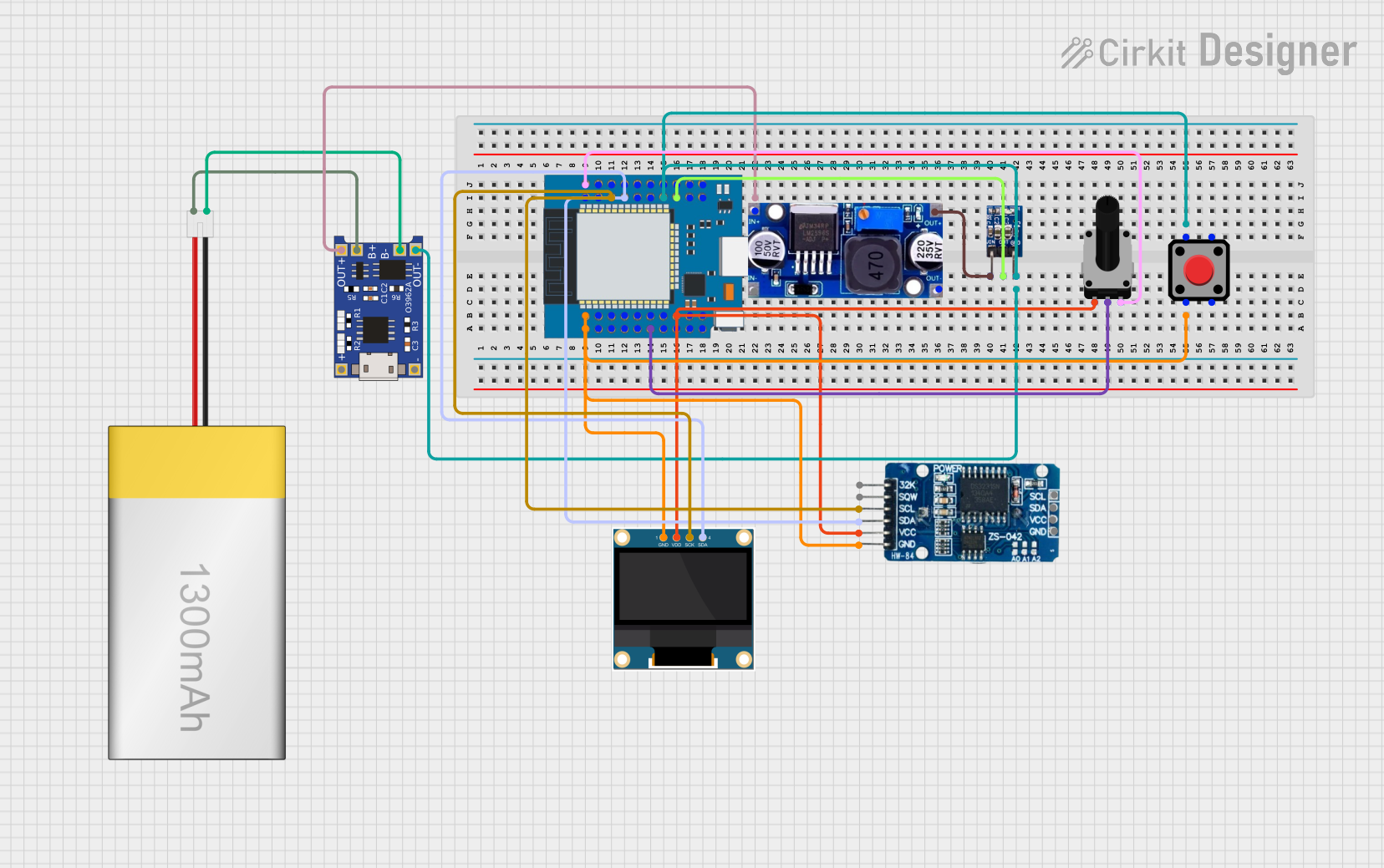
 Open Project in Cirkit Designer
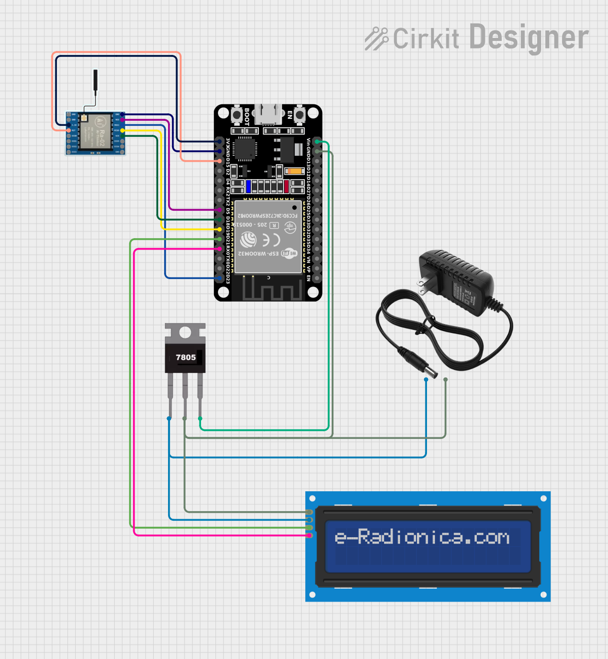
 Open Project in Cirkit Designer
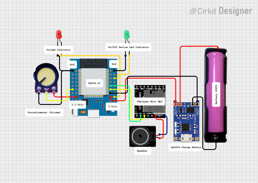
 Open Project in Cirkit Designer
Explore Projects Built with Lolin32 ESP32

 Open Project in Cirkit Designer
 Open Project in Cirkit Designer
 Open Project in Cirkit Designer
 Open Project in Cirkit Designer
Common Applications and Use Cases
- Smart home devices
- Wireless sensors and data logging
- IoT prototypes
- Wearable electronics
- Remote control and monitoring systems
Technical Specifications
Key Technical Details
- Microcontroller: Espressif ESP32
- Operating Voltage: 3.3V
- Input Voltage: 7-12V via Vin pin, 5V via micro USB port
- Digital I/O Pins: 26
- Analog Input Pins: 12 (ADC 12-bit)
- Analog Outputs: 2 (DAC 10-bit)
- Flash Memory: 4MB
- SRAM: 520 KB
- Clock Speed: 240MHz
- Wi-Fi: 802.11 b/g/n
- Bluetooth: v4.2 BR/EDR and BLE
- USB-to-UART Bridge: CP2104
Pin Configuration and Descriptions
| Pin Number | Function | Description |
|---|---|---|
| 1 | GND | Ground |
| 2 | 3V3 | 3.3V power supply input |
| 3 | EN | Reset (active low) |
| 4-17 | GPIO 1-14 | General Purpose Input/Output pins |
| 18-19 | ADC1-2 | Analog to Digital Converter channels 1-2 |
| 20-21 | DAC1-2 | Digital to Analog Converter channels 1-2 |
| 22 | 5V | 5V power supply input via USB |
| 23 | VIN | 7-12V power supply input |
| 24 | TX0 | UART0 transmit |
| 25 | RX0 | UART0 receive |
| 26 | SDA | I2C data |
| 27 | SCL | I2C clock |
| 28 | GND | Ground |
Usage Instructions
How to Use the Lolin32 ESP32 in a Circuit
Powering the Board:
- You can power the Lolin32 ESP32 via the micro USB port or through the Vin pin with a 7-12V power supply.
- Ensure that the power supply is stable and within the specified voltage range to prevent damage.
Connecting to a Computer:
- Connect the board to your computer using a micro USB cable.
- The CP2104 USB-to-UART Bridge will allow the board to communicate with your computer for programming and serial monitoring.
Programming the Board:
- The Lolin32 ESP32 can be programmed using the Arduino IDE or other development environments that support the ESP32.
- Select the appropriate board and port in your IDE before uploading your code.
Using I/O Pins:
- The GPIO pins can be used for digital input and output.
- The ADC pins are for reading analog voltages, and the DAC pins can output analog voltages.
Important Considerations and Best Practices
- Always disconnect the board from power sources before making or altering connections.
- Use a current limiting resistor when connecting LEDs to GPIO pins.
- Avoid drawing more than 12 mA from any GPIO pin.
- Ensure that the input voltage to the ADC does not exceed 3.3V.
Troubleshooting and FAQs
Common Issues
Board not recognized by computer:
- Ensure the micro USB cable is properly connected and is not a charge-only cable.
- Check that the CP2104 drivers are installed on your computer.
Unable to upload code:
- Select the correct board and port in your IDE.
- Hold down the "BOOT" button on the board when starting the upload process.
Unexpected behavior in circuits:
- Double-check wiring and connections.
- Ensure power supply is stable and within the specified range.
Solutions and Tips for Troubleshooting
- If the board is not recognized, try using a different USB port or cable.
- For driver issues, download and install the latest CP2104 drivers from the manufacturer's website.
- When encountering errors during code upload, check the IDE's console output for specific error messages that can guide troubleshooting.
Example Code for Arduino UNO
Here is a simple example of how to blink an LED connected to a GPIO pin on the Lolin32 ESP32 using the Arduino IDE:
// Define the LED pin
const int ledPin = 5; // Use GPIO number where your LED is connected

void setup() {
  // Initialize the LED pin as an output
  pinMode(ledPin, OUTPUT);
}

void loop() {
  // Turn the LED on (HIGH is the voltage level)
  digitalWrite(ledPin, HIGH);
  // Wait for a second
  delay(1000);
  // Turn the LED off by making the voltage LOW
  digitalWrite(ledPin, LOW);
   // Wait for a second
  delay(1000);
}
Remember to configure the Arduino IDE with the correct board settings for the Lolin32 ESP32 before uploading the code. This example assumes that an LED with an appropriate current-limiting resistor is connected to GPIO 5.
Note: This documentation is a general guide and does not cover all aspects of the Lolin32 ESP32. For more detailed information, refer to the manufacturer's datasheet and technical resources.