How to Use DC-DC_CONVERTER: Examples, Pinouts, and Specs
Introduction
A DC-DC Converter is an essential electronic component designed to convert a source of direct current (DC) from one voltage level to another. It is a type of power converter that efficiently provides the required voltage for electronic devices. DC-DC converters are commonly used in battery-powered equipment, laptops, adjustable power supplies, and as power regulators in various electronic circuits.
Explore Projects Built with DC-DC_CONVERTER


Explore Projects Built with DC-DC_CONVERTER
Common Applications and Use Cases
- Portable Electronics: Mobile phones, tablets, and laptops.
- Automotive: Powering electronics in vehicles from a 12V or 24V battery.
- Industrial: Providing isolated power supplies for sensors and actuators.
- Telecommunications: Powering wireless and RF devices.
- Aerospace: Satellite and avionics power systems.
Technical Specifications
Key Technical Details
- Input Voltage Range: The range of voltage the converter can accept.
- Output Voltage Range: The range of voltage the converter can output.
- Maximum Output Current: The maximum current the converter can provide.
- Efficiency: The ratio of output power to input power, typically expressed as a percentage.
- Switching Frequency: The frequency at which the converter's internal switch operates.
- Operating Temperature Range: The range of ambient temperatures over which the converter can operate reliably.
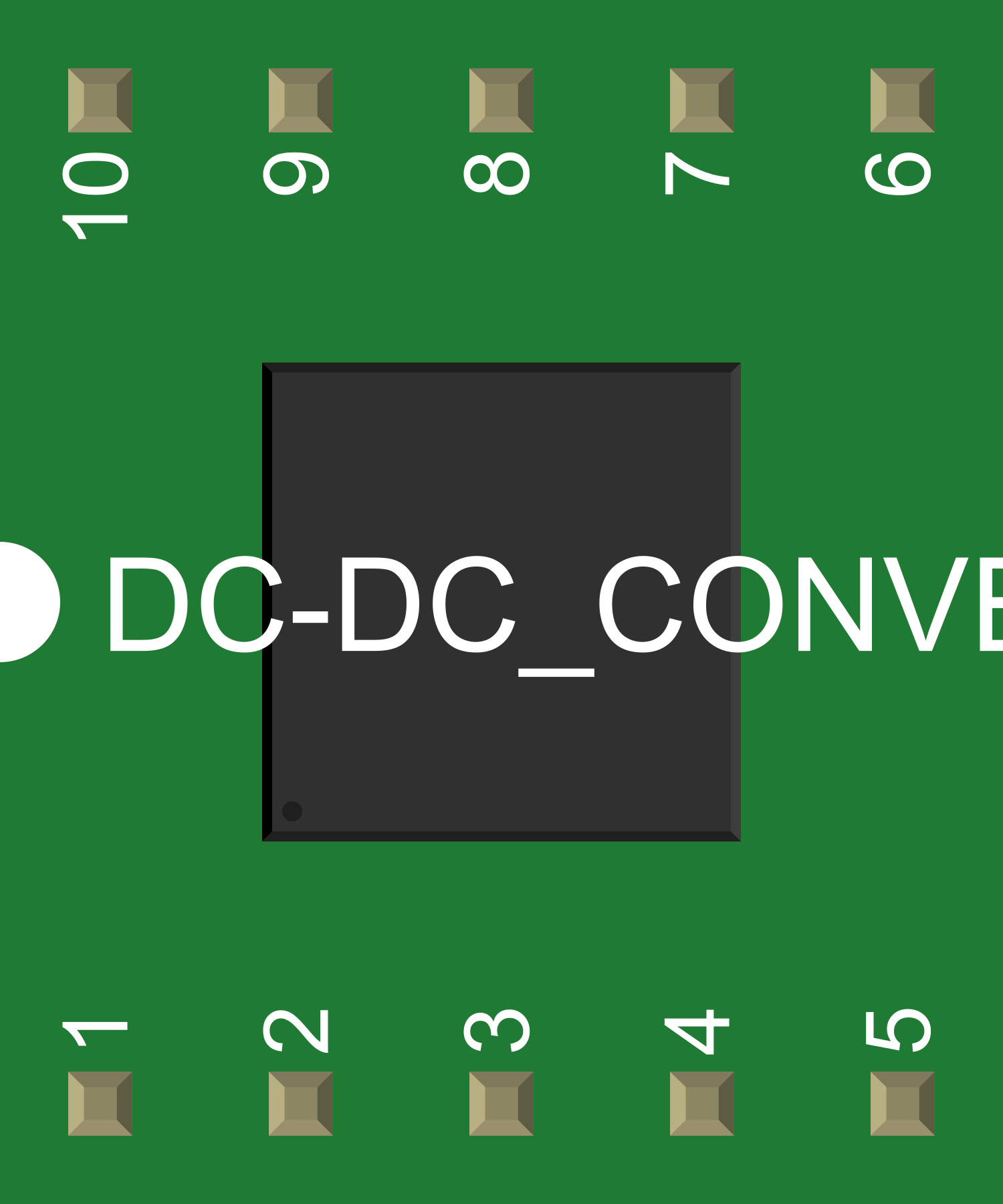
Pin Configuration and Descriptions
| Pin Number | Name | Description |
|---|---|---|
| 1 | VIN | Input voltage to the converter |
| 2 | GND | Ground reference for the circuit |
| 3 | VOUT | Output voltage from the converter |
| 4 | EN | Enable pin for turning the converter on/off |
| 5 | FB | Feedback pin for output voltage regulation |
Usage Instructions
How to Use the Component in a Circuit
- Connecting Input Voltage: Connect the input voltage source to the VIN and GND pins, ensuring it is within the specified input voltage range.
- Output Voltage: Connect the load to the VOUT and GND pins. The output voltage should be set according to the requirements of the load.
- Enable Pin: The EN pin can be used to turn the converter on or off. This can be connected to a logic high signal to enable the converter or left unconnected if not used.
- Feedback Pin: The FB pin is used for regulation purposes and is typically connected through a voltage divider to set the desired output voltage.
Important Considerations and Best Practices
- Heat Dissipation: Ensure adequate cooling for the converter, as they can generate significant heat during operation.
- Input/Output Capacitors: Use capacitors at the input and output to minimize voltage ripple and improve stability.
- Load Regulation: Be aware of the converter's load regulation specifications to ensure output voltage remains within acceptable limits under varying load conditions.
- Switching Noise: Be mindful of the switching frequency and potential electromagnetic interference (EMI) in sensitive applications.
Troubleshooting and FAQs
Common Issues Users Might Face
- Insufficient Output Voltage: Check if the input voltage is within the specified range and that the load does not exceed the maximum output current.
- Overheating: Ensure proper heat sinking and airflow around the converter.
- Noise Issues: Verify that the layout minimizes noise and that adequate filtering is in place.
Solutions and Tips for Troubleshooting
- Output Voltage Adjustment: If the output voltage is not correct, check the feedback resistor values and connections.
- Thermal Management: If overheating occurs, improve heat dissipation with a heat sink or by improving airflow.
- EMI Mitigation: Use shielding, proper grounding, and layout techniques to reduce EMI.
FAQs
Q: Can I use a DC-DC converter to charge a battery? A: Yes, but ensure the converter's output voltage and current are suitable for the battery.
Q: How do I choose the right DC-DC converter for my application? A: Consider the input and output voltage ranges, maximum output current, efficiency, and physical size for your application.
Q: What is the difference between isolated and non-isolated DC-DC converters? A: Isolated converters provide electrical isolation between input and output, while non-isolated converters do not.
Example Code for Arduino UNO
// Example code to control a DC-DC converter with an Arduino UNO
const int enablePin = 3; // Connect to the EN pin of the DC-DC converter

void setup() {
  pinMode(enablePin, OUTPUT);
  // Start with the converter disabled
  digitalWrite(enablePin, LOW);
}

void loop() {
  // Enable the DC-DC converter
  digitalWrite(enablePin, HIGH);
  delay(5000); // Wait for 5 seconds

  // Disable the DC-DC converter
  digitalWrite(enablePin, LOW);
  delay(5000); // Wait for 5 seconds
}
Note: The above code is a simple example to turn the DC-DC converter on and off using the Arduino's digital pin connected to the converter's enable pin. Ensure that the logic level voltage of the Arduino is compatible with the enable pin voltage level of the DC-DC converter.