Cirkit Designer Logo
Cirkit Designer
Your all-in-one circuit design IDE
Home / 
Component Documentation

How to Use 9-40V to 6V3A step down converter: Examples, Pinouts, and Specs

Image of 9-40V to 6V3A step down converter
Cirkit Designer LogoDesign with 9-40V to 6V3A step down converter in Cirkit Designer

Introduction

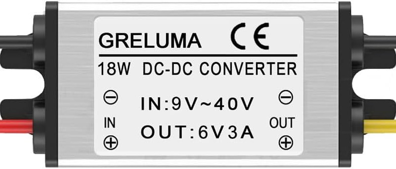
The Greluma ZL963LUM is a high-efficiency DC-DC step-down converter designed to reduce an input voltage range of 9V to 40V to a stable output of 6V with a maximum current of 3A. This component is ideal for powering devices that require a lower voltage, such as microcontrollers, sensors, and small electronic devices. Its compact design and robust performance make it suitable for a wide range of applications, including automotive electronics, industrial equipment, and DIY projects.

Explore Projects Built with 9-40V to 6V3A step down converter

Use Cirkit Designer to design, explore, and prototype these projects online. Some projects support real-time simulation. Click "Open Project" to start designing instantly!
Battery-Powered DC-DC Converter System for Multi-Voltage Power Distribution
Image of test 1 ih: A project utilizing 9-40V to 6V3A step down converter in a practical application
This circuit converts a 38.5V battery output to multiple lower voltage levels using a series of DC-DC converters and a power module. It includes an emergency stop switch for safety and distributes power to various components such as a relay module, USB ports, and a bus servo adaptor.
Cirkit Designer LogoOpen Project in Cirkit Designer
Battery-Powered UPS with Step-Down Buck Converter and BMS
Image of Mini ups: A project utilizing 9-40V to 6V3A step down converter in a practical application
This circuit is a power management system that steps down a 240V AC input to a lower DC voltage using a buck converter, which then powers a 40W UPS. The UPS is controlled by a rocker switch and is backed up by a battery management system (BMS) connected to three 3.7V batteries in series, ensuring continuous power supply.
Cirkit Designer LogoOpen Project in Cirkit Designer
USB Power Supply with Overcurrent Protection
Image of USB Charging port: A project utilizing 9-40V to 6V3A step down converter in a practical application
This circuit is designed to step down voltage from a 12V battery to a lower voltage suitable for USB devices. It includes a buck converter connected to the battery through a fuse and fuse holder for overcurrent protection. The output of the buck converter is connected to a USB female port, providing a regulated power supply for USB-powered devices.
Cirkit Designer LogoOpen Project in Cirkit Designer
Voltage Regulation System with MT3608 Boost and LM2596 Buck Converters
Image of solar system router ups: A project utilizing 9-40V to 6V3A step down converter in a practical application
This circuit consists of two MT3608 boost converters and an LM2596 step-down module, each connected to separate 12V power supplies. The MT3608 modules are configured to step up the voltage from their respective power supplies, while the LM2596 module steps down the voltage from a 12V battery. Diodes are used to ensure correct current flow direction, potentially for protection or isolation between different parts of the circuit.
Cirkit Designer LogoOpen Project in Cirkit Designer

Explore Projects Built with 9-40V to 6V3A step down converter

Use Cirkit Designer to design, explore, and prototype these projects online. Some projects support real-time simulation. Click "Open Project" to start designing instantly!
Image of test 1 ih: A project utilizing 9-40V to 6V3A step down converter in a practical application
Battery-Powered DC-DC Converter System for Multi-Voltage Power Distribution
This circuit converts a 38.5V battery output to multiple lower voltage levels using a series of DC-DC converters and a power module. It includes an emergency stop switch for safety and distributes power to various components such as a relay module, USB ports, and a bus servo adaptor.
Cirkit Designer LogoOpen Project in Cirkit Designer
Image of Mini ups: A project utilizing 9-40V to 6V3A step down converter in a practical application
Battery-Powered UPS with Step-Down Buck Converter and BMS
This circuit is a power management system that steps down a 240V AC input to a lower DC voltage using a buck converter, which then powers a 40W UPS. The UPS is controlled by a rocker switch and is backed up by a battery management system (BMS) connected to three 3.7V batteries in series, ensuring continuous power supply.
Cirkit Designer LogoOpen Project in Cirkit Designer
Image of USB Charging port: A project utilizing 9-40V to 6V3A step down converter in a practical application
USB Power Supply with Overcurrent Protection
This circuit is designed to step down voltage from a 12V battery to a lower voltage suitable for USB devices. It includes a buck converter connected to the battery through a fuse and fuse holder for overcurrent protection. The output of the buck converter is connected to a USB female port, providing a regulated power supply for USB-powered devices.
Cirkit Designer LogoOpen Project in Cirkit Designer
Image of solar system router ups: A project utilizing 9-40V to 6V3A step down converter in a practical application
Voltage Regulation System with MT3608 Boost and LM2596 Buck Converters
This circuit consists of two MT3608 boost converters and an LM2596 step-down module, each connected to separate 12V power supplies. The MT3608 modules are configured to step up the voltage from their respective power supplies, while the LM2596 module steps down the voltage from a 12V battery. Diodes are used to ensure correct current flow direction, potentially for protection or isolation between different parts of the circuit.
Cirkit Designer LogoOpen Project in Cirkit Designer

Common Applications and Use Cases

  • Powering microcontrollers (e.g., Arduino, Raspberry Pi) and sensors.
  • Supplying stable voltage to LED strips or small motors.
  • Automotive applications for converting car battery voltage to 6V.
  • DIY electronics projects requiring a reliable 6V power source.

Technical Specifications

The following table outlines the key technical details of the Greluma ZL963LUM step-down converter:

Parameter Value
Input Voltage Range 9V to 40V
Output Voltage 6V
Maximum Output Current 3A
Efficiency Up to 95%
Operating Temperature -40°C to +85°C
Dimensions 45mm x 25mm x 15mm
Weight 20g

Pin Configuration and Descriptions

The ZL963LUM has four pins for input and output connections. The table below describes each pin:

Pin Name Description
VIN+ Positive input voltage terminal (9V to 40V).
VIN- Negative input voltage terminal (ground).
VOUT+ Positive output voltage terminal (6V).
VOUT- Negative output voltage terminal (ground).

Usage Instructions

How to Use the Component in a Circuit

  1. Connect the Input Voltage:
    • Attach the VIN+ pin to the positive terminal of your input power source (9V to 40V).
    • Connect the VIN- pin to the ground of your input power source.
  2. Connect the Output Voltage:
    • Attach the VOUT+ pin to the positive terminal of the device you want to power.
    • Connect the VOUT- pin to the ground of the device.
  3. Verify Connections:
    • Double-check all connections to ensure proper polarity and avoid short circuits.
  4. Power On:
    • Turn on the input power source. The converter will regulate the input voltage to provide a stable 6V output.

Important Considerations and Best Practices

  • Input Voltage Range: Ensure the input voltage is within the specified range (9V to 40V). Exceeding this range may damage the converter.
  • Heat Dissipation: At high currents, the converter may generate heat. Use proper ventilation or a heatsink if necessary.
  • Load Requirements: Do not exceed the maximum output current of 3A to prevent overheating or damage.
  • Polarity Protection: Double-check the polarity of input and output connections to avoid damage to the converter or connected devices.

Example: Using with an Arduino UNO

The ZL963LUM can be used to power an Arduino UNO by providing a stable 6V supply. Below is an example circuit and Arduino code to blink an LED:

Circuit Connections

  1. Connect the VIN+ and VIN- pins of the converter to a 12V DC power source.
  2. Connect the VOUT+ pin to the Arduino UNO's Vin pin.
  3. Connect the VOUT- pin to the Arduino UNO's GND pin.
  4. Connect an LED to pin 13 of the Arduino UNO with a 220-ohm resistor in series.

Arduino Code

// Simple LED blink example for Arduino UNO
// This code assumes an LED is connected to pin 13 with a 220-ohm resistor.

void setup() {
  pinMode(13, OUTPUT); // Set pin 13 as an output pin
}

void loop() {
  digitalWrite(13, HIGH); // Turn the LED on
  delay(1000);            // Wait for 1 second
  digitalWrite(13, LOW);  // Turn the LED off
  delay(1000);            // Wait for 1 second
}

Troubleshooting and FAQs

Common Issues Users Might Face

  1. No Output Voltage:
    • Cause: Incorrect input voltage or loose connections.
    • Solution: Verify that the input voltage is within the 9V to 40V range and check all connections.
  2. Overheating:
    • Cause: Excessive load or poor ventilation.
    • Solution: Ensure the load does not exceed 3A and provide adequate cooling.
  3. Output Voltage Fluctuations:
    • Cause: Unstable input voltage or insufficient input filtering.
    • Solution: Use a stable power source and consider adding a capacitor (e.g., 100µF) across the input terminals.

Solutions and Tips for Troubleshooting

  • Check Polarity: Ensure the input and output connections are correctly polarized.
  • Measure Voltages: Use a multimeter to verify the input and output voltages.
  • Inspect for Damage: Look for signs of physical damage, such as burnt components or broken solder joints.

By following this documentation, users can effectively integrate the Greluma ZL963LUM step-down converter into their projects and troubleshoot common issues with ease.