How to Use Red Pushbutton: Examples, Pinouts, and Specs
Introduction
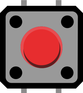
A red pushbutton is a simple yet essential electronic component used to control the flow of electricity in a circuit. It is a momentary switch, which means it only closes the circuit while the button is being pressed. Upon release, the switch returns to its default open state. This type of button is often red to signify an action such as stopping or starting a process, making it a popular choice for emergency stop functions, user interfaces, and control panels.
Explore Projects Built with Red Pushbutton

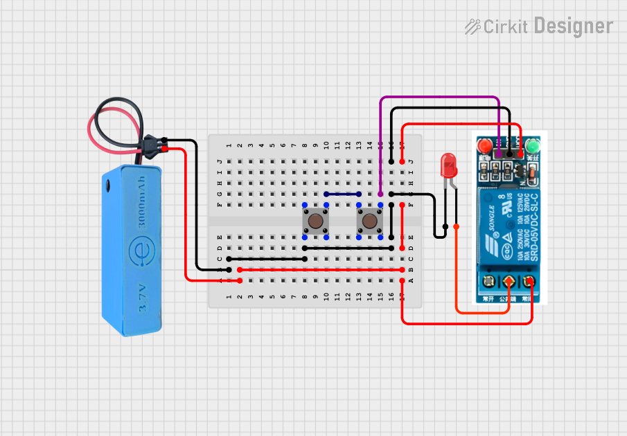
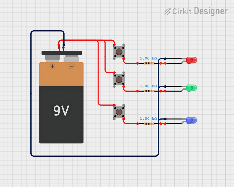
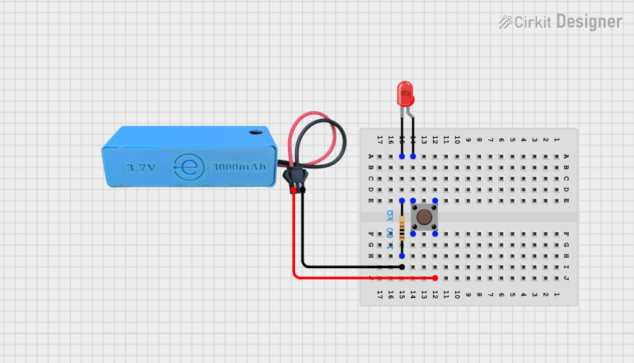
Explore Projects Built with Red Pushbutton
Common Applications and Use Cases
- Initiating a process, such as starting a machine or a motor
- User input for interactive projects
- Reset or interrupt functions in electronic devices
- As a user interface button on electronic instruments
- Emergency stop buttons in industrial settings
Technical Specifications
Key Technical Details
- Rated Voltage: Typically 3V to 6V for low-power applications
- Rated Current: Usually around 50mA to 200mA
- Contact Resistance: Typically less than 50 mΩ
- Insulation Resistance: Greater than 100 MΩ
- Operating Force: Generally between 100g to 300g
- Mechanical Life: Often rated for 100,000 to 1,000,000 cycles
- Operating Temperature: Usually between -20°C to +70°C
Pin Configuration and Descriptions
| Pin Number | Description |
|---|---|
| 1 | Normally Open (NO) |
| 2 | Common (COM) |
Usage Instructions
How to Use the Component in a Circuit
- Identify the Pins: Locate the Normally Open (NO) and Common (COM) pins on the pushbutton.
- Circuit Integration: Connect the COM pin to one side of the power source. The NO pin should be connected to the load (e.g., LED, relay, or input pin on a microcontroller).
- Debounce: Since mechanical switches tend to bounce (multiple open/close actions) when pressed, it's important to implement a debounce mechanism either through hardware (using capacitors and resistors) or software when using with a microcontroller.
Important Considerations and Best Practices
- Current Limiting: Always use a current-limiting resistor with the load to prevent excessive current from flowing when the button is pressed.
- Mounting: Ensure the pushbutton is securely mounted to prevent movement and ensure reliable operation.
- Contact Material: Be aware of the contact material, as some materials are better suited for low-power applications while others can handle higher currents.
Example Code for Arduino UNO
// Define the pin connected to the pushbutton
const int buttonPin = 2;
// Define the pin connected to the LED
const int ledPin =  13;
// Variable for reading the pushbutton status
int buttonState = 0;

void setup() {
  // Initialize the LED pin as an output
  pinMode(ledPin, OUTPUT);
  // Initialize the pushbutton pin as an input
  pinMode(buttonPin, INPUT);
}

void loop(){
  // Read the state of the pushbutton value
  buttonState = digitalRead(buttonPin);

  // Check if the pushbutton is pressed. If it is, the buttonState is HIGH
  if (buttonState == HIGH) {
    // Turn on the LED
    digitalWrite(ledPin, HIGH);
  } else {
    // Turn off the LED
    digitalWrite(ledPin, LOW);
  }
}
Troubleshooting and FAQs
Common Issues Users Might Face
- Button Does Not Respond: Ensure the button is properly connected and there are no loose wires. Check the current-limiting resistor and replace if necessary.
- Intermittent Operation: This could be due to switch bounce. Implement a debounce mechanism to resolve this issue.
- Button Sticks: If the button sticks in the pressed position, check for any obstructions or misalignment in the button mechanism.
Solutions and Tips for Troubleshooting
- Debounce Mechanism: Implement a debounce mechanism in your circuit or code to prevent false triggering due to switch bounce.
- Regular Inspection: Periodically inspect the pushbutton for wear and tear, especially if it's used frequently.
- Test with a Multimeter: Use a multimeter to check the continuity of the pushbutton when pressed. If there is no continuity, the pushbutton may need to be replaced.
FAQs
Q: Can I use a red pushbutton with any voltage? A: No, you should use the pushbutton within its rated voltage and current specifications to prevent damage.
Q: How do I know if my pushbutton is normally open or normally closed? A: A normally open pushbutton will not conduct electricity until pressed. You can test this with a multimeter set to the continuity function.
Q: Can I use the pushbutton without a microcontroller? A: Yes, pushbuttons can be used in simple circuits without a microcontroller, such as turning on an LED or activating a relay.