
How to Use CY8CKIT-062S2-AI: Examples, Pinouts, and Specs
 Design with CY8CKIT-062S2-AI in Cirkit Designer
Introduction
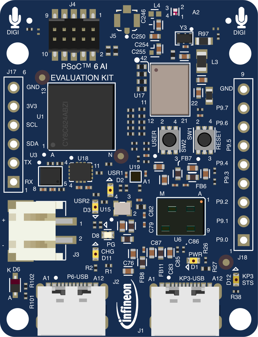
The CY8CKIT-062S2-AI is a development kit manufactured by Infineon (formerly Cypress Semiconductor) designed for building AI and machine learning applications. At its core is the PSoC 62 microcontroller, which combines a dual-core architecture (Arm® Cortex®-M4 and Cortex®-M0+) with integrated Wi-Fi and Bluetooth connectivity. This makes it an ideal platform for prototyping and developing IoT solutions.
The kit includes a variety of onboard sensors, interfaces, and expansion options, enabling developers to experiment with AI, machine learning, and IoT applications. Its versatility and ease of use make it suitable for both beginners and experienced developers.
Explore Projects Built with CY8CKIT-062S2-AI
 Open Project in Cirkit Designer
 Open Project in Cirkit Designer
 Open Project in Cirkit Designer
 Open Project in Cirkit Designer
Explore Projects Built with CY8CKIT-062S2-AI
Open Project in Cirkit DesignerOpen Project in Cirkit DesignerOpen Project in Cirkit DesignerOpen Project in Cirkit DesignerCommon Applications
- IoT (Internet of Things): Smart home devices, industrial IoT, and connected appliances.
- AI and Machine Learning: Edge AI applications, predictive maintenance, and data analysis.
- Wireless Connectivity: Prototyping Wi-Fi and Bluetooth-enabled devices.
- Sensor Integration: Applications requiring environmental, motion, or proximity sensing.
Technical Specifications
Key Features
- Microcontroller: PSoC 62 (CY8C624ABZI-S2D44)
- Dual-core: Arm® Cortex®-M4 (150 MHz) and Cortex®-M0+ (100 MHz)
- 1 MB Flash, 288 KB SRAM
- Connectivity:
- Wi-Fi: 802.11b/g/n
- Bluetooth: BLE 5.0
- Onboard Sensors:
- Ambient light sensor
- 6-axis motion sensor (accelerometer + gyroscope)
- Temperature and humidity sensor
- Interfaces:
- CapSense® capacitive touch interface
- USB Type-C for power and programming
- Arduino-compatible headers for expansion
- Power Supply:
- USB Type-C (5V)
- External power supply (1.8V to 3.3V)
- Operating Voltage: 1.8V to 3.3V
- Dimensions: 100 mm x 50 mm
Pin Configuration and Descriptions
The CY8CKIT-062S2-AI features multiple headers and connectors. Below is a summary of the key pin configurations:
Arduino-Compatible Header
| Pin Name | Function | Description |
|---|---|---|
| A0-A5 | Analog Input | Analog pins for sensor input or ADC use |
| D0-D13 | Digital I/O | General-purpose digital I/O pins |
| SDA/SCL | I2C Communication | I2C data and clock lines |
| VIN | Power Input | External power input (up to 5V) |
| GND | Ground | Common ground for the circuit |
PSoC 62 GPIO Header
| Pin Name | Function | Description |
|---|---|---|
| P0.x-P12.x | General Purpose I/O (GPIO) | Configurable as digital or analog pins |
| VDD | Power Supply | 3.3V power output |
| GND | Ground | Common ground for the circuit |
USB Type-C Connector
| Pin Name | Function | Description |
|---|---|---|
| VBUS | Power Input | Supplies 5V to the board |
| D+ / D- | USB Data Lines | USB communication for programming/debug |
| GND | Ground | Common ground for USB |
Usage Instructions
How to Use the CY8CKIT-062S2-AI in a Circuit
Powering the Board:
- Connect the board to a computer or power source using the USB Type-C cable.
- Alternatively, supply power through the VIN pin (up to 5V).
Programming the Board:
- Use the ModusToolbox IDE (recommended by Infineon) for programming and debugging.
- Connect the board via USB and select the appropriate target device in the IDE.
Connecting Sensors and Peripherals:
- Use the Arduino-compatible headers to connect external sensors or modules.
- For I2C devices, connect to the SDA and SCL pins.
- For analog sensors, use the A0-A5 pins.
Wireless Connectivity:
- Configure Wi-Fi and Bluetooth settings using the provided libraries in ModusToolbox.
- Use the onboard antenna for wireless communication.
Important Considerations and Best Practices
- Power Supply: Ensure the board is powered within the specified voltage range (1.8V to 3.3V for GPIO, 5V for USB).
- Static Protection: Handle the board with care to avoid damage from electrostatic discharge (ESD).
- Firmware Updates: Regularly update the firmware using ModusToolbox to access the latest features and bug fixes.
- Debugging: Use the onboard debug interface for troubleshooting and performance analysis.
Example Code for Arduino-Compatible Sensors
Below is an example of interfacing a temperature sensor (I2C-based) with the CY8CKIT-062S2-AI:
#include <Wire.h>

// I2C address of the temperature sensor
#define TEMP_SENSOR_ADDR 0x48

void setup() {
  Wire.begin(); // Initialize I2C communication
  Serial.begin(9600); // Start serial communication for debugging
  Serial.println("Temperature Sensor Example");
}

void loop() {
  Wire.beginTransmission(TEMP_SENSOR_ADDR); // Start communication with sensor
  Wire.write(0x00); // Request temperature data
  Wire.endTransmission();

  Wire.requestFrom(TEMP_SENSOR_ADDR, 2); // Request 2 bytes of data
  if (Wire.available() == 2) {
    int tempData = (Wire.read() << 8) | Wire.read(); // Combine MSB and LSB
    float temperature = tempData * 0.0625; // Convert to Celsius
    Serial.print("Temperature: ");
    Serial.print(temperature);
    Serial.println(" °C");
  }

  delay(1000); // Wait 1 second before next reading
}
Troubleshooting and FAQs
Common Issues
Board Not Detected by ModusToolbox:
- Ensure the USB cable is properly connected and functional.
- Verify that the correct drivers are installed for the CY8CKIT-062S2-AI.
Wi-Fi or Bluetooth Not Working:
- Check the firmware version and update if necessary.
- Ensure the onboard antenna is not obstructed.
Sensor Data Not Reading Correctly:
- Verify the sensor connections and ensure proper pin alignment.
- Check the I2C address or communication protocol of the sensor.
Power Issues:
- Ensure the board is powered within the specified voltage range.
- Check for loose connections or faulty power sources.
Solutions and Tips
- Debugging Tools: Use the onboard debugger and ModusToolbox's debugging features to identify issues in your code.
- Documentation: Refer to the official Infineon documentation for detailed technical resources.
- Community Support: Join the Infineon developer forums for additional help and resources.
This concludes the documentation for the CY8CKIT-062S2-AI development kit.