
How to Use qw: Examples, Pinouts, and Specs
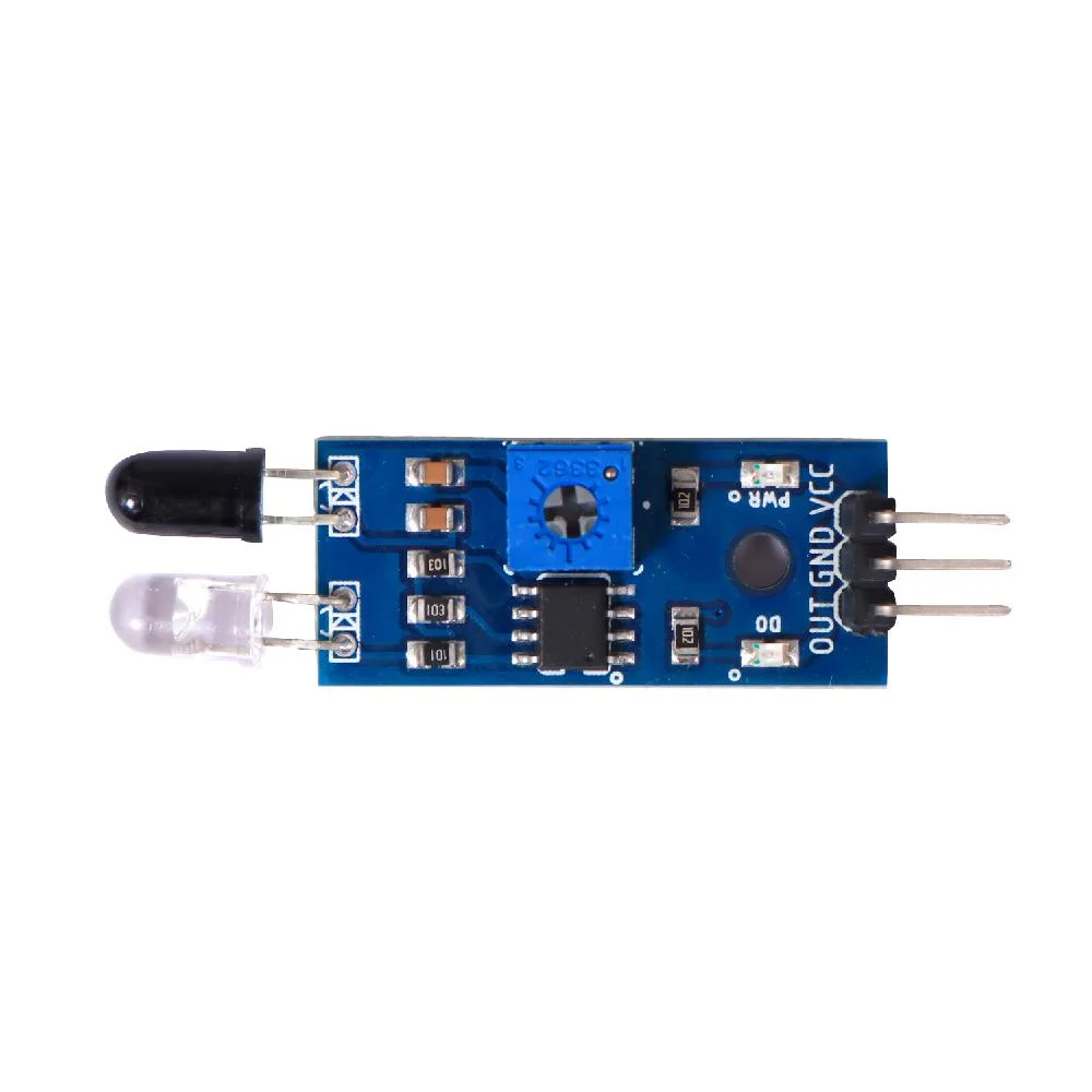
 Design with qw in Cirkit Designer
Introduction
The QW component is a semiconductor device designed to allow current to flow in only one direction. It is a fundamental element in electronics, often used in rectifier circuits to convert alternating current (AC) to direct current (DC). This unidirectional behavior is essential in applications such as power supply units, battery charging systems, and any circuit requiring a steady DC voltage.
Explore Projects Built with qw
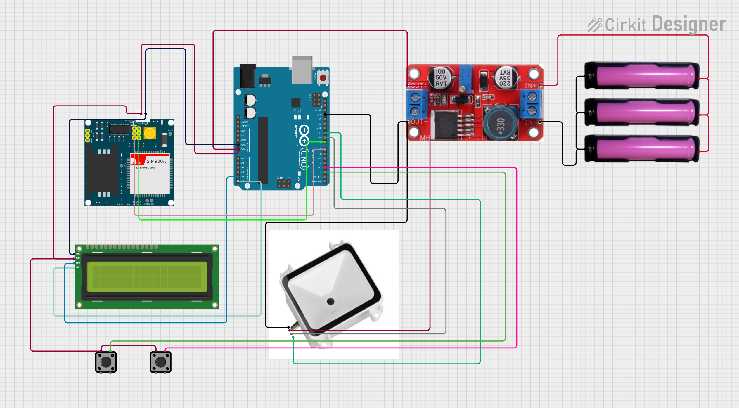
 Open Project in Cirkit Designer
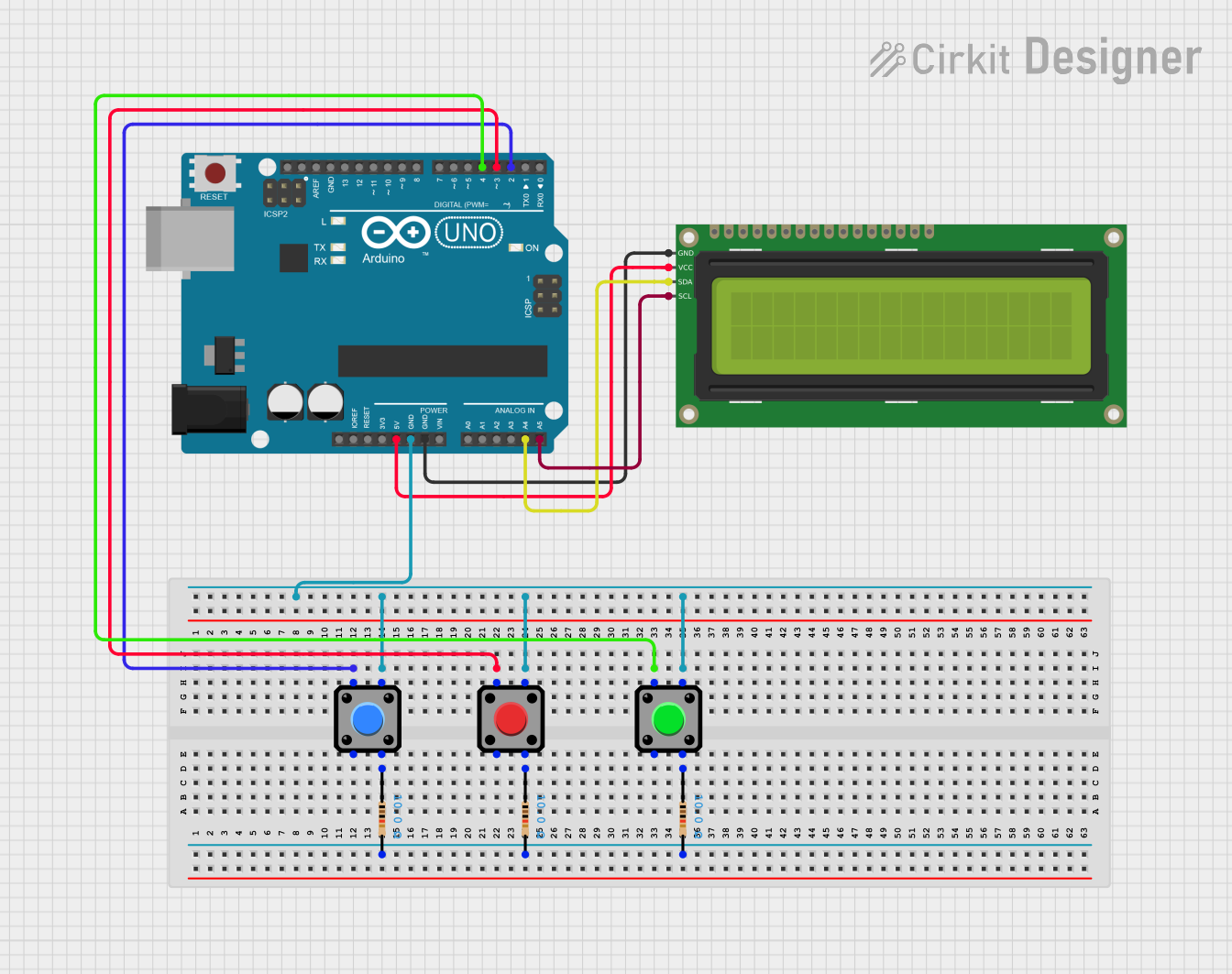
 Open Project in Cirkit Designer
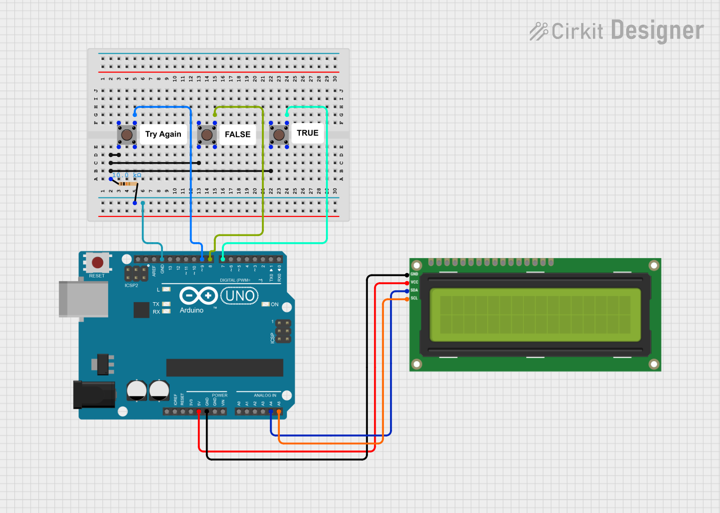
 Open Project in Cirkit Designer
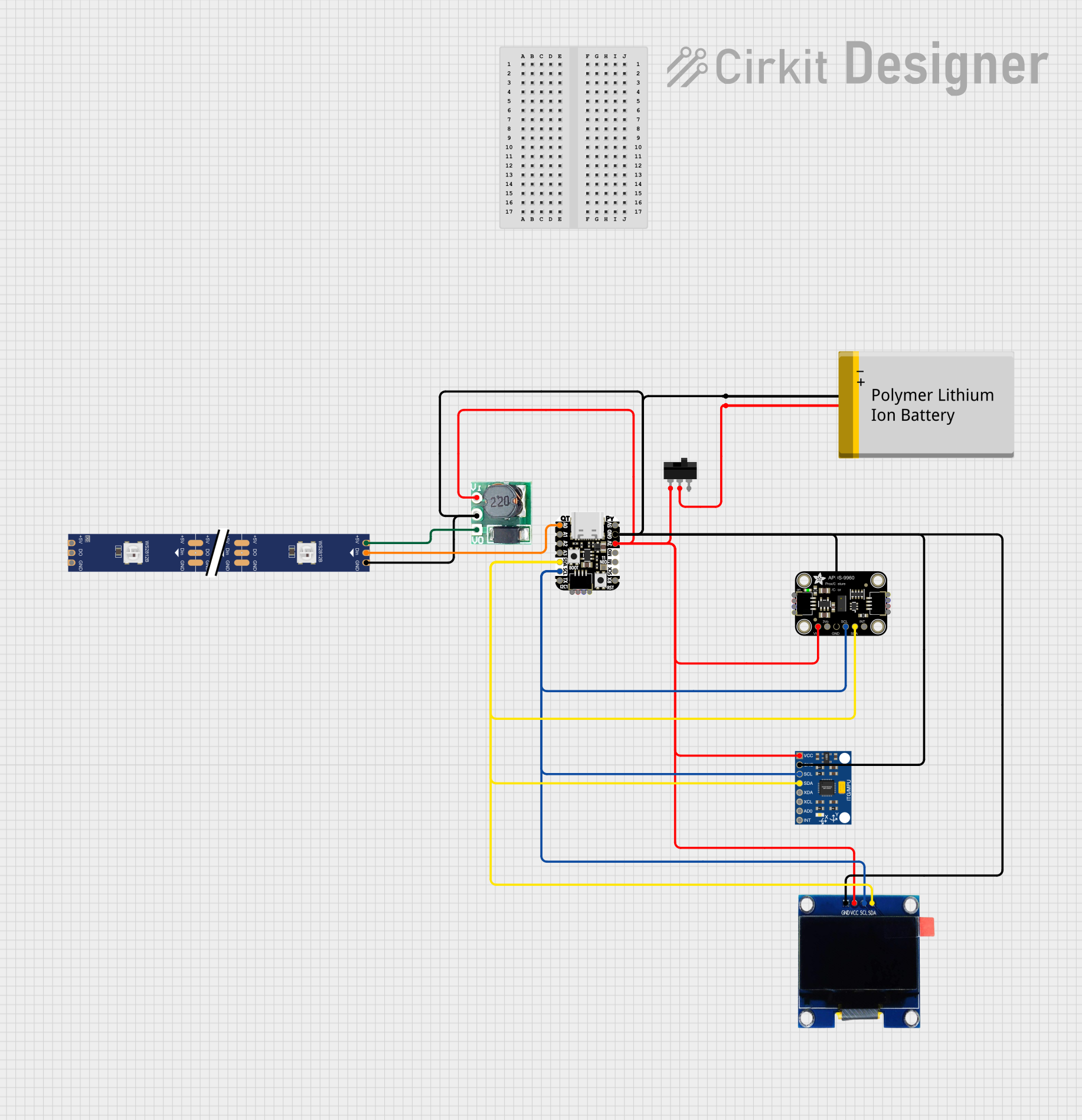
 Open Project in Cirkit Designer
Explore Projects Built with qw

 Open Project in Cirkit Designer
 Open Project in Cirkit Designer
 Open Project in Cirkit Designer
 Open Project in Cirkit Designer
Technical Specifications
General Characteristics
- Manufacturer: AS
- Part ID: ZX
- Type: Rectifier
- Mounting Type: [Through-hole/Surface-mount] (Specify the actual mounting type)
- Package: [TO-220/DO-35/etc.] (Specify the actual package)
Electrical Ratings
| Parameter | Value | Unit | Conditions/Notes |
|---|---|---|---|
| Maximum Repetitive Reverse Voltage (Vrrm) | XX | V | Maximum voltage the component can withstand in the reverse direction |
| Average Forward Current (If(AV)) | XX | A | Maximum average current the component can conduct |
| Peak Forward Surge Current (Ifsm) | XX | A | Maximum current during a surge or pulse |
| Forward Voltage Drop (Vf) | X.XX | V | Typical voltage drop at specified forward current |
| Reverse Current (Ir) | X.XX | µA | Current leakage in the reverse direction at Vrrm |
| Operating Junction Temperature (Tj) | -XX to +XXX | °C | Temperature range over which the device operates safely |
Pin Configuration
| Pin Number | Name | Description |
|---|---|---|
| 1 | Anode | Connects to the positive side of the circuit |
| 2 | Cathode | Connects to the negative side of the circuit |
Note: The actual pin configuration may vary based on the package type.
Usage Instructions
Incorporating into a Circuit
- Orientation: Ensure the QW component is oriented correctly, with the anode connected to the positive side of the circuit and the cathode to the negative side.
- Heat Management: Depending on the current rating and application, a heatsink may be necessary to dissipate heat and maintain the component within its operating temperature range.
- Voltage and Current Ratings: Do not exceed the specified voltage and current ratings to prevent damage to the component.
- Filtering: In rectifier applications, use capacitors to filter the output and reduce ripple voltage.
Best Practices
- Use a current-limiting resistor to protect the QW component from excessive current.
- Employ a snubber circuit to protect against voltage spikes, especially in inductive loads.
- Ensure proper soldering techniques to avoid cold joints or overheating the component.
Example Circuit: Rectifier with Arduino UNO
// Example code for using the QW component with an Arduino UNO
// to create a simple rectifier circuit.

void setup() {
  // Initialize the digital pin as an output.
  pinMode(2, OUTPUT); // Pin 2 connected to the anode of QW
}

void loop() {
  digitalWrite(2, HIGH); // Set the pin high to allow current flow
  delay(1000);           // Wait for a second
  digitalWrite(2, LOW);  // Set the pin low to stop current flow
  delay(1000);           // Wait for a second
}
Note: This is a simplified example. In a real-world application, the QW component would be part of a more complex circuit.
Troubleshooting and FAQs
Common Issues
- No Output Voltage: Ensure the QW component is correctly oriented and not installed backward.
- Excessive Heat: Check if the current through the component exceeds the average forward current rating. If so, reduce the load or use a component with a higher rating.
- Intermittent Functionality: Inspect solder joints and connections for reliability. Also, check for any signs of physical damage to the component.
FAQs
Q: Can the QW component be used for high-frequency applications? A: It depends on the specific model of the QW component. Check the manufacturer's datasheet for frequency ratings.
Q: What happens if the reverse voltage exceeds the maximum rating? A: Exceeding the maximum reverse voltage may lead to a breakdown and permanent damage to the component.
Q: Is it necessary to use a heatsink with the QW component? A: It depends on the current it is carrying and the ambient temperature. If the component is operating near its maximum ratings, a heatsink is recommended.
For further assistance, please refer to the manufacturer's datasheet or contact technical support.