How to Use Spikonado MotionCore: Examples, Pinouts, and Specs
Introduction
The Spikonado MotionCore is a state-of-the-art motion control system developed by Spikonado Technologies. It is designed to deliver precise movement and automation capabilities, making it an ideal choice for robotics, industrial automation, and other applications requiring real-time motion tracking and control. The MotionCore leverages advanced algorithms to ensure smooth, accurate, and efficient operation, even in complex environments.
Explore Projects Built with Spikonado MotionCore
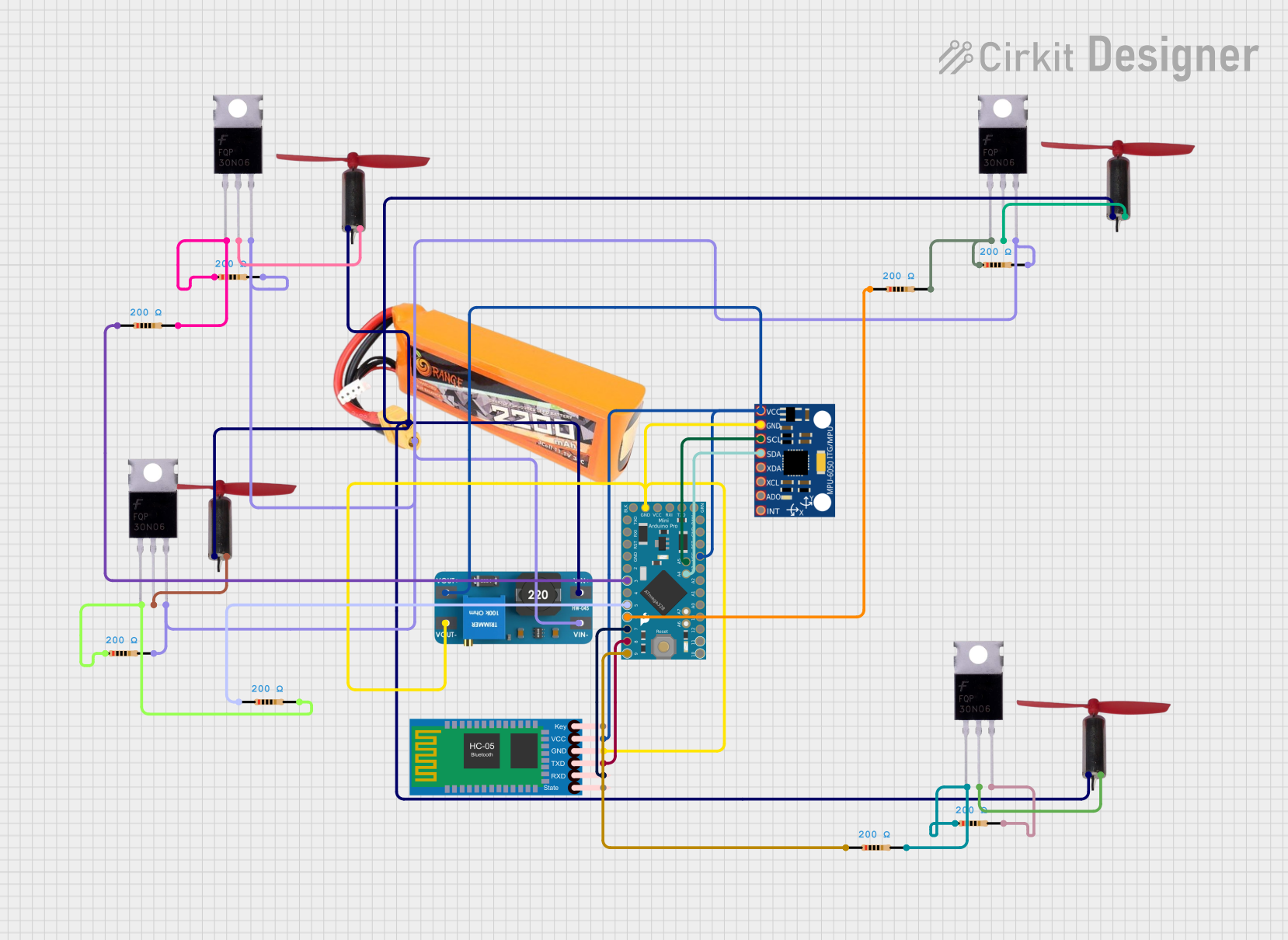
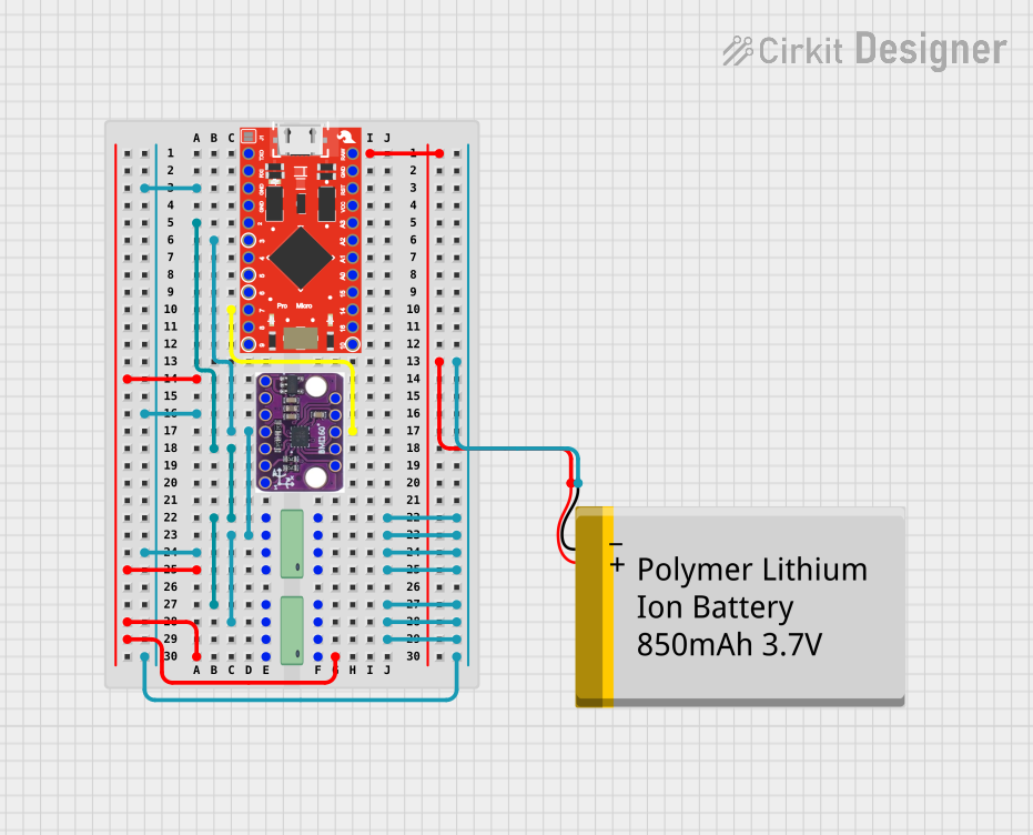
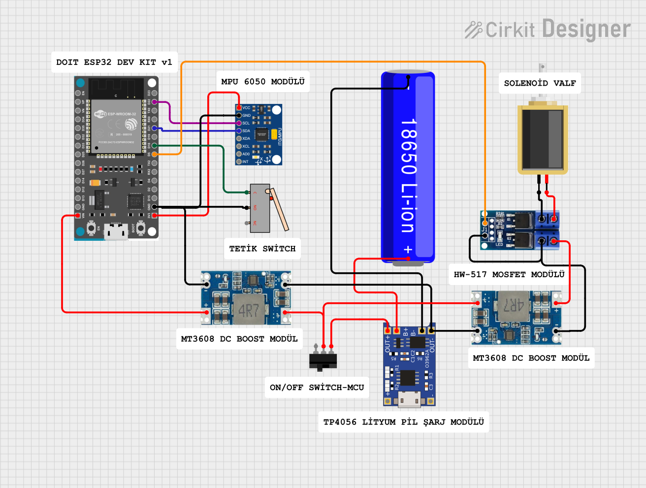
Explore Projects Built with Spikonado MotionCore
Common Applications and Use Cases
- Robotic arms for manufacturing and assembly lines
- CNC machines and 3D printers
- Automated guided vehicles (AGVs) and drones
- Precision positioning systems in medical devices
- Industrial conveyor systems
Technical Specifications
The Spikonado MotionCore is engineered to meet the demands of high-performance motion control. Below are its key technical specifications:
General Specifications
| Parameter | Value |
|---|---|
| Operating Voltage | 12V to 48V DC |
| Maximum Current | 10A per motor channel |
| Supported Motors | Stepper, DC, and BLDC motors |
| Communication Protocols | UART, I2C, SPI, CAN |
| Control Resolution | 0.01 mm or 0.1° (angular) |
| Operating Temperature | -20°C to 70°C |
| Dimensions | 100mm x 60mm x 20mm |
| Weight | 150g |
Pin Configuration and Descriptions
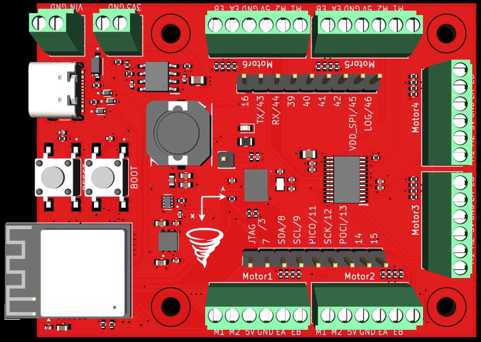
The MotionCore features a 20-pin interface for versatile connectivity. Below is the pinout:
| Pin Number | Name | Description |
|---|---|---|
| 1 | VIN | Power input (12V to 48V DC) |
| 2 | GND | Ground connection |
| 3 | MOTOR_A+ | Positive terminal for Motor A |
| 4 | MOTOR_A- | Negative terminal for Motor A |
| 5 | MOTOR_B+ | Positive terminal for Motor B |
| 6 | MOTOR_B- | Negative terminal for Motor B |
| 7 | UART_TX | UART transmit pin |
| 8 | UART_RX | UART receive pin |
| 9 | I2C_SCL | I2C clock line |
| 10 | I2C_SDA | I2C data line |
| 11 | SPI_MOSI | SPI Master Out Slave In |
| 12 | SPI_MISO | SPI Master In Slave Out |
| 13 | SPI_SCK | SPI clock |
| 14 | SPI_CS | SPI chip select |
| 15 | CAN_H | CAN bus high |
| 16 | CAN_L | CAN bus low |
| 17 | EN_A | Enable signal for Motor A |
| 18 | EN_B | Enable signal for Motor B |
| 19 | DIR_A | Direction control for Motor A |
| 20 | DIR_B | Direction control for Motor B |
Usage Instructions
The Spikonado MotionCore is designed for easy integration into a variety of systems. Follow the steps below to use it effectively:
Step 1: Powering the MotionCore
- Connect a DC power supply (12V to 48V) to the VIN and GND pins.
- Ensure the power supply can provide sufficient current for the connected motors.
Step 2: Connecting Motors
- Attach the motor wires to the corresponding MOTOR_A+, MOTOR_A-, MOTOR_B+, and MOTOR_B- pins.
- Use the EN_A and EN_B pins to enable or disable the motors as needed.
Step 3: Communication Setup
- Choose a communication protocol (UART, I2C, SPI, or CAN) based on your system requirements.
- For UART, connect the UART_TX and UART_RX pins to the microcontroller.
- For I2C, connect the I2C_SCL and I2C_SDA pins, ensuring proper pull-up resistors are used.
- For SPI, connect SPI_MOSI, SPI_MISO, SPI_SCK, and SPI_CS.
- For CAN, connect CAN_H and CAN_L to the CAN bus.
Step 4: Programming and Control
- Use the Spikonado MotionCore library (available on the Spikonado Technologies website) to control the motion system.
- Below is an example of controlling a stepper motor using an Arduino UNO and the MotionCore via UART:
#include <SoftwareSerial.h>

// Define UART pins for communication with MotionCore
SoftwareSerial MotionCoreSerial(10, 11); // RX, TX

void setup() {
  // Initialize serial communication
  Serial.begin(9600); // For debugging
  MotionCoreSerial.begin(115200); // MotionCore default baud rate

  // Send initialization command to MotionCore
  MotionCoreSerial.println("INIT"); // Initialize the MotionCore
  delay(100);

  // Set motor parameters (example: speed and direction)
  MotionCoreSerial.println("SET_MOTOR_A_SPEED 100"); // Set speed for Motor A
  MotionCoreSerial.println("SET_MOTOR_A_DIR 1");    // Set direction for Motor A
}

void loop() {
  // Example: Start Motor A
  MotionCoreSerial.println("START_MOTOR_A");
  delay(5000); // Run for 5 seconds

  // Stop Motor A
  MotionCoreSerial.println("STOP_MOTOR_A");
  delay(2000); // Pause for 2 seconds
}
Important Considerations
- Always verify the motor specifications to ensure compatibility with the MotionCore.
- Use proper heat dissipation methods if operating at high currents for extended periods.
- Avoid reversing the power supply polarity to prevent damage to the MotionCore.
Troubleshooting and FAQs
Common Issues and Solutions
Issue: Motors do not move after powering the MotionCore.
- Solution: Check the power supply voltage and current. Ensure the motors are properly connected to the correct pins.
Issue: Communication with the MotionCore fails.
- Solution: Verify the communication protocol settings (e.g., baud rate for UART). Ensure the correct pins are connected.
Issue: Motors vibrate but do not rotate.
- Solution: Check the motor wiring and ensure the enable and direction signals are correctly configured.
Issue: Overheating of the MotionCore.
- Solution: Ensure proper ventilation and consider adding a heatsink or fan for cooling.
FAQs
Q: Can the MotionCore control multiple motors simultaneously?
A: Yes, it supports up to two motors (Motor A and Motor B) simultaneously.Q: Is the MotionCore compatible with brushless motors?
A: Yes, it supports stepper, DC, and BLDC motors.Q: What is the maximum cable length for communication?
A: For UART and I2C, keep the cable length under 1 meter for reliable communication. For CAN, longer distances (up to 40 meters) are supported.Q: Does the MotionCore come with a software library?
A: Yes, the library is available for download on the Spikonado Technologies website.
By following this documentation, you can effectively integrate and operate the Spikonado MotionCore in your projects. For further assistance, refer to the official Spikonado Technologies support resources.