How to Use Arduino 101: Examples, Pinouts, and Specs
Introduction
The Arduino 101 is a microcontroller board based on the Intel Curie module. It combines the simplicity of the Arduino platform with advanced features such as built-in Bluetooth Low Energy (BLE) capabilities and a 6-axis accelerometer/gyroscope. This makes it an excellent choice for projects involving wireless communication, motion sensing, and IoT applications. The board is compatible with the Arduino IDE, making it accessible to both beginners and experienced developers.
Explore Projects Built with Arduino 101

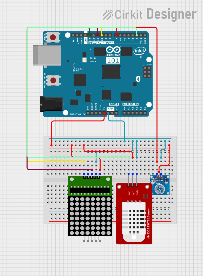
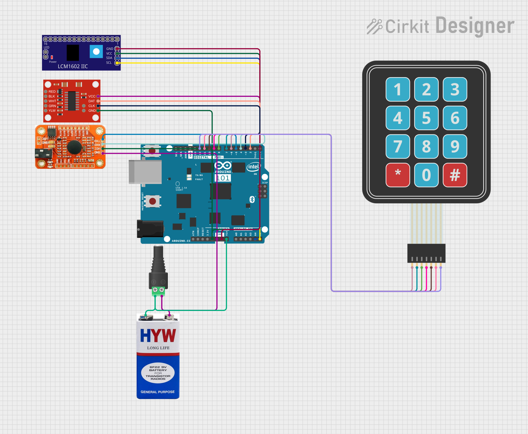
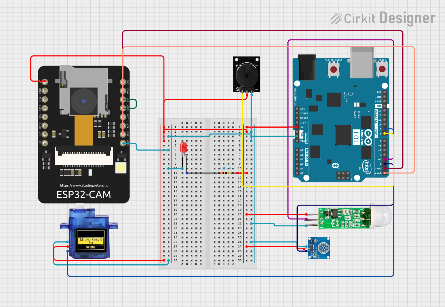
Explore Projects Built with Arduino 101
Common Applications and Use Cases
- IoT (Internet of Things) devices and prototypes
- Wearable technology
- Motion tracking and gesture recognition
- Wireless communication via BLE
- Robotics and automation projects
- Data logging and sensor interfacing
Technical Specifications
Key Technical Details
- Microcontroller: Intel Curie module (32-bit Intel Quark SE SoC)
- Operating Voltage: 3.3V
- Input Voltage (recommended): 7-12V
- Input Voltage (limit): 6-20V
- Digital I/O Pins: 14 (4 of which support PWM output)
- Analog Input Pins: 6
- DC Current per I/O Pin: 20 mA
- Flash Memory: 196 KB
- SRAM: 24 KB
- EEPROM: None (emulated in flash memory)
- Clock Speed: 32 MHz
- Built-in Features: Bluetooth Low Energy (BLE), 6-axis accelerometer/gyroscope
- USB Connector: Micro-USB
- Dimensions: 68.6 mm x 53.4 mm
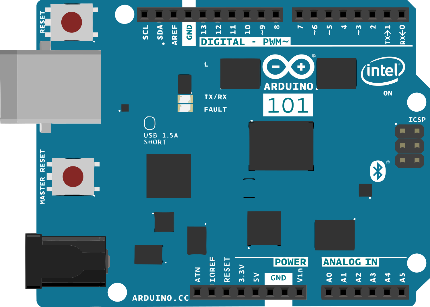
Pin Configuration and Descriptions
The Arduino 101 features a variety of pins for interfacing with external components. Below is a detailed description of the pin layout:
| Pin | Type | Description |
|---|---|---|
| Digital 0-13 | Digital I/O | General-purpose digital input/output pins. Pins 3, 5, 6, and 9 support PWM. |
| Analog 0-5 | Analog Input | Used for reading analog signals (0-1023 range). |
| GND | Ground | Ground connection for the circuit. |
| 3.3V | Power Output | Provides 3.3V regulated power. |
| 5V | Power Output | Provides 5V regulated power. |
| VIN | Power Input | Input voltage to the board when using an external power source (7-12V). |
| AREF | Analog Reference | Reference voltage for analog inputs. |
| I2C (A4, A5) | Communication | SDA (A4) and SCL (A5) pins for I2C communication. |
| UART (0, 1) | Communication | TX (0) and RX (1) pins for serial communication. |
| BLE | Wireless | Built-in Bluetooth Low Energy for wireless communication. |
| IMU | Sensor | Built-in 6-axis accelerometer/gyroscope for motion sensing. |
Usage Instructions
How to Use the Arduino 101 in a Circuit
Powering the Board:
- Connect the Arduino 101 to your computer via the Micro-USB cable for programming and power.
- Alternatively, use an external power supply (7-12V) connected to the VIN pin or the DC power jack.
Programming the Board:
- Install the Arduino IDE on your computer.
- Add the Intel Curie Boards package via the Arduino Boards Manager.
- Select "Arduino/Genuino 101" from the Tools > Board menu.
- Write your code and upload it to the board using the USB connection.
Using BLE:
- The Arduino 101 includes built-in BLE capabilities. Use the
CurieBLElibrary to create BLE peripherals or central devices. - Pair the board with a BLE-compatible device (e.g., smartphone) for wireless communication.
- The Arduino 101 includes built-in BLE capabilities. Use the
Using the IMU:
- The 6-axis accelerometer/gyroscope can be accessed using the
CurieIMUlibrary. - Use it for motion tracking, gesture recognition, or orientation sensing.
- The 6-axis accelerometer/gyroscope can be accessed using the
Example: Reading Accelerometer Data
Here is an example of how to read accelerometer data using the CurieIMU library:
#include <CurieIMU.h>

void setup() {
  Serial.begin(9600); // Initialize serial communication
  while (!Serial);    // Wait for the serial port to open

  CurieIMU.begin();   // Initialize the IMU
  Serial.println("IMU initialized!");

  // Set accelerometer range to ±4g
  CurieIMU.setAccelerometerRange(4);
}

void loop() {
  int ax, ay, az;

  // Read accelerometer values
  CurieIMU.readAccelerometer(ax, ay, az);

  // Print the values to the Serial Monitor
  Serial.print("Accelerometer: ");
  Serial.print("X = "); Serial.print(ax);
  Serial.print(", Y = "); Serial.print(ay);
  Serial.print(", Z = "); Serial.println(az);

  delay(500); // Wait for 500ms before the next reading
}
Important Considerations and Best Practices
- Voltage Levels: The Arduino 101 operates at 3.3V logic levels. Ensure that any external components connected to the I/O pins are compatible with 3.3V.
- Power Supply: Avoid exceeding the recommended input voltage range (7-12V) to prevent damage to the board.
- BLE Range: The BLE range is limited to approximately 10-15 meters. Ensure there are no significant obstacles between the board and the paired device.
- Libraries: Use the
CurieBLEandCurieIMUlibraries for BLE and IMU functionality, respectively. These libraries are specifically designed for the Arduino 101.
Troubleshooting and FAQs
Common Issues and Solutions
Problem: The board is not recognized by the Arduino IDE.
Solution:- Ensure the correct drivers are installed.
- Check that the Intel Curie Boards package is installed in the Boards Manager.
- Verify that the correct COM port is selected in the Tools > Port menu.
Problem: BLE connection is unstable or not working.
Solution:- Ensure the BLE device is within range (10-15 meters).
- Check that the
CurieBLElibrary is correctly implemented in your code. - Restart both the Arduino 101 and the BLE device to reset the connection.
Problem: IMU readings are inconsistent or incorrect.
Solution:- Calibrate the IMU using the
CurieIMUlibrary's calibration functions. - Ensure the board is placed on a stable surface during initialization.
- Calibrate the IMU using the
Problem: The board does not power on.
Solution:- Check the power source and connections.
- Ensure the input voltage is within the recommended range (7-12V).
- Try using a different USB cable or power adapter.
FAQs
Q: Can I use the Arduino 101 with 5V sensors?
A: Yes, but you will need a level shifter to convert the 5V signals to 3.3V.Q: Is the Arduino 101 compatible with all Arduino shields?
A: The Arduino 101 is compatible with most Arduino shields, but ensure the shield operates at 3.3V logic levels.Q: How do I update the firmware on the Arduino 101?
A: Use the "Firmware Updater" tool in the Arduino IDE to update the Curie module firmware.Q: Can I use the Arduino 101 for battery-powered projects?
A: Yes, you can use a battery pack (7-12V) connected to the VIN pin or DC power jack.