Cirkit Designer Logo
Cirkit Designer
Your all-in-one circuit design IDE
Home / 
Component Documentation

How to Use gx12 - 7 pin male connector: Examples, Pinouts, and Specs

Image of gx12 - 7 pin male connector
Cirkit Designer LogoDesign with gx12 - 7 pin male connector in Cirkit Designer

Introduction

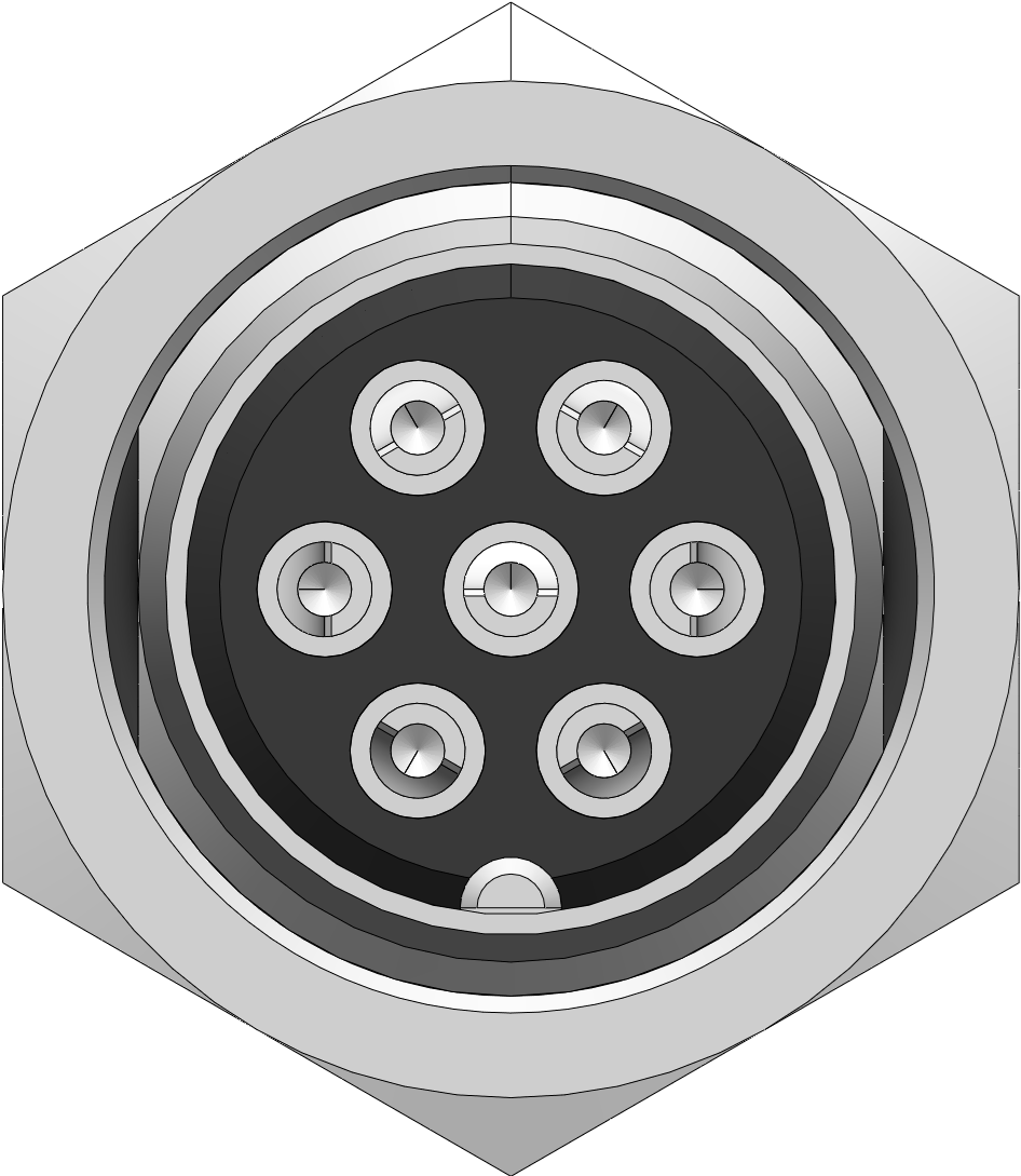
The GX12-7 pin male connector is a circular electrical connector featuring 7 pins. It is widely used for connecting power and signal lines in various electronic applications. Its robust design and secure locking mechanism make it ideal for industrial environments, lighting systems, and other equipment requiring reliable electrical connections. The connector is often paired with its female counterpart to establish a secure and durable connection.

Explore Projects Built with gx12 - 7 pin male connector

Use Cirkit Designer to design, explore, and prototype these projects online. Some projects support real-time simulation. Click "Open Project" to start designing instantly!
5-Pin Connector Synchronization Circuit
Image of UMB_Cable: A project utilizing gx12 - 7 pin male connector in a practical application
This circuit consists of four 5-pin connectors, where two of the connectors are fully interconnected pin-to-pin. The purpose of this setup could be to create a parallel connection between the two 5-pin connectors, possibly for signal distribution or redundancy.
Cirkit Designer LogoOpen Project in Cirkit Designer
Dual 5V Power Supply Distribution Circuit with Toggle Switch Control
Image of rfdriver: A project utilizing gx12 - 7 pin male connector in a practical application
This circuit consists of two 5V 5A power supplies connected to an AC wall plug point, providing DC output through a 12-way connector. The ground connections from both power supplies are interconnected and also connected to the ground pins of two toggle switches. The DC outputs from the power supplies are separately connected to different pins on the 12-way connector, with each power supply output being switchable via one of the toggle switches.
Cirkit Designer LogoOpen Project in Cirkit Designer
Cellular-Enabled IoT Device with Real-Time Clock and Power Management
Image of LRCM PHASE 2 BASIC: A project utilizing gx12 - 7 pin male connector in a practical application
This circuit features a LilyGo-SIM7000G module for cellular communication and GPS functionality, interfaced with an RTC DS3231 for real-time clock capabilities. It includes voltage sensing through two voltage sensor modules, and uses an 8-channel opto-coupler for isolating different parts of the circuit. Power management is handled by a buck converter connected to a DC power source and batteries, with a fuse for protection and a rocker switch for on/off control. Additionally, there's an LED for indication purposes.
Cirkit Designer LogoOpen Project in Cirkit Designer
Satellite-Based Timing and Navigation System with SDR and Atomic Clock Synchronization
Image of GPS 시스템 측정 구성도_Confirm: A project utilizing gx12 - 7 pin male connector in a practical application
This circuit appears to be a complex system involving power supply management, GPS and timing synchronization, and data communication. It includes a SI-TEX G1 Satellite Compass for GPS data, an XHTF1021 Atomic Rubidium Clock for precise timing, and Ettus USRP B200 units for software-defined radio communication. Power is supplied through various SMPS units and distributed via terminal blocks and DC jacks. Data communication is facilitated by Beelink MINI S12 N95 computers, RS232 splitters, and a 1000BASE-T Media Converter for network connectivity. RF Directional Couplers are used to interface antennas with the USRP units, and the entire system is likely contained within cases for protection and organization.
Cirkit Designer LogoOpen Project in Cirkit Designer

Explore Projects Built with gx12 - 7 pin male connector

Use Cirkit Designer to design, explore, and prototype these projects online. Some projects support real-time simulation. Click "Open Project" to start designing instantly!
Image of UMB_Cable: A project utilizing gx12 - 7 pin male connector in a practical application
5-Pin Connector Synchronization Circuit
This circuit consists of four 5-pin connectors, where two of the connectors are fully interconnected pin-to-pin. The purpose of this setup could be to create a parallel connection between the two 5-pin connectors, possibly for signal distribution or redundancy.
Cirkit Designer LogoOpen Project in Cirkit Designer
Image of rfdriver: A project utilizing gx12 - 7 pin male connector in a practical application
Dual 5V Power Supply Distribution Circuit with Toggle Switch Control
This circuit consists of two 5V 5A power supplies connected to an AC wall plug point, providing DC output through a 12-way connector. The ground connections from both power supplies are interconnected and also connected to the ground pins of two toggle switches. The DC outputs from the power supplies are separately connected to different pins on the 12-way connector, with each power supply output being switchable via one of the toggle switches.
Cirkit Designer LogoOpen Project in Cirkit Designer
Image of LRCM PHASE 2 BASIC: A project utilizing gx12 - 7 pin male connector in a practical application
Cellular-Enabled IoT Device with Real-Time Clock and Power Management
This circuit features a LilyGo-SIM7000G module for cellular communication and GPS functionality, interfaced with an RTC DS3231 for real-time clock capabilities. It includes voltage sensing through two voltage sensor modules, and uses an 8-channel opto-coupler for isolating different parts of the circuit. Power management is handled by a buck converter connected to a DC power source and batteries, with a fuse for protection and a rocker switch for on/off control. Additionally, there's an LED for indication purposes.
Cirkit Designer LogoOpen Project in Cirkit Designer
Image of GPS 시스템 측정 구성도_Confirm: A project utilizing gx12 - 7 pin male connector in a practical application
Satellite-Based Timing and Navigation System with SDR and Atomic Clock Synchronization
This circuit appears to be a complex system involving power supply management, GPS and timing synchronization, and data communication. It includes a SI-TEX G1 Satellite Compass for GPS data, an XHTF1021 Atomic Rubidium Clock for precise timing, and Ettus USRP B200 units for software-defined radio communication. Power is supplied through various SMPS units and distributed via terminal blocks and DC jacks. Data communication is facilitated by Beelink MINI S12 N95 computers, RS232 splitters, and a 1000BASE-T Media Converter for network connectivity. RF Directional Couplers are used to interface antennas with the USRP units, and the entire system is likely contained within cases for protection and organization.
Cirkit Designer LogoOpen Project in Cirkit Designer

Common Applications:

  • Industrial equipment and machinery
  • LED lighting systems
  • Robotics and automation
  • Audio and video equipment
  • DIY electronics projects

Technical Specifications

Key Technical Details:

  • Connector Type: Circular, 7-pin male
  • Material: Metal shell with nickel plating (corrosion-resistant)
  • Pin Material: Brass with silver or gold plating (for better conductivity)
  • Rated Voltage: 250V AC/DC
  • Rated Current: 5A per pin
  • Operating Temperature Range: -20°C to +85°C
  • Mounting Style: Panel mount or cable mount
  • Locking Mechanism: Threaded coupling for secure connections
  • Contact Resistance: ≤ 5 mΩ
  • Insulation Resistance: ≥ 1000 MΩ at 500V DC

Pin Configuration and Descriptions:

The GX12-7 pin male connector has 7 pins arranged in a circular pattern. Below is the pinout description:

Pin Number Description Common Use
1 Power Supply (+) Positive voltage input
2 Power Supply (-) Ground or negative voltage
3 Signal Line 1 Data or control signal
4 Signal Line 2 Data or control signal
5 Signal Line 3 Data or control signal
6 Signal Line 4 Data or control signal
7 Signal Line 5 Data or control signal

Note: The actual pin assignments may vary depending on the application. Always refer to the specific wiring diagram for your project.

Usage Instructions

How to Use the GX12-7 Pin Male Connector in a Circuit:

  1. Wiring the Connector:

    • Solder the wires to the appropriate pins on the back of the connector. Ensure proper insulation to avoid short circuits.
    • Use heat shrink tubing or electrical tape to secure and protect the soldered connections.
  2. Mounting the Connector:

    • For panel mounting, drill a hole in the panel to fit the connector's diameter (12mm).
    • Secure the connector using the provided nut and washer.
  3. Connecting to the Female Connector:

    • Align the male and female connectors using the alignment notch.
    • Screw the threaded coupling to lock the connectors securely.
  4. Testing the Connection:

    • Use a multimeter to verify continuity and ensure proper connections before powering the circuit.

Important Considerations and Best Practices:

  • Polarity: Double-check the polarity of power connections to avoid damage to the circuit.
  • Strain Relief: Use strain relief mechanisms to prevent stress on the wires and solder joints.
  • Environmental Protection: If used in harsh environments, consider sealing the connector with waterproofing materials.
  • Pinout Verification: Always verify the pinout with the datasheet or wiring diagram specific to your application.

Example: Connecting to an Arduino UNO

The GX12-7 pin male connector can be used to interface multiple signals with an Arduino UNO. Below is an example of how to connect the connector to an Arduino for reading multiple sensor inputs:

Wiring:

  • Pin 1: Connect to Arduino 5V
  • Pin 2: Connect to Arduino GND
  • Pins 3-7: Connect to Arduino digital pins (e.g., D2, D3, D4, D5, D6)

Sample Code:

// Example code for reading signals from a GX12-7 pin connector
// connected to an Arduino UNO. Pins 3-7 are used for digital inputs.

const int pin3 = 2; // Signal Line 1 connected to Arduino pin D2
const int pin4 = 3; // Signal Line 2 connected to Arduino pin D3
const int pin5 = 4; // Signal Line 3 connected to Arduino pin D4
const int pin6 = 5; // Signal Line 4 connected to Arduino pin D5
const int pin7 = 6; // Signal Line 5 connected to Arduino pin D6

void setup() {
  // Initialize pins as inputs
  pinMode(pin3, INPUT);
  pinMode(pin4, INPUT);
  pinMode(pin5, INPUT);
  pinMode(pin6, INPUT);
  pinMode(pin7, INPUT);

  // Start serial communication for debugging
  Serial.begin(9600);
}

void loop() {
  // Read the state of each pin and print to the Serial Monitor
  int signal1 = digitalRead(pin3);
  int signal2 = digitalRead(pin4);
  int signal3 = digitalRead(pin5);
  int signal4 = digitalRead(pin6);
  int signal5 = digitalRead(pin7);

  Serial.print("Signal 1: "); Serial.println(signal1);
  Serial.print("Signal 2: "); Serial.println(signal2);
  Serial.print("Signal 3: "); Serial.println(signal3);
  Serial.print("Signal 4: "); Serial.println(signal4);
  Serial.print("Signal 5: "); Serial.println(signal5);

  delay(1000); // Wait for 1 second before reading again
}

Troubleshooting and FAQs

Common Issues and Solutions:

  1. Loose Connection:

    • Ensure the threaded coupling is tightly secured.
    • Check for proper alignment of the male and female connectors.
  2. No Signal or Power:

    • Verify the soldered connections for continuity using a multimeter.
    • Check the power supply and ensure correct polarity.
  3. Short Circuits:

    • Inspect for solder bridges between adjacent pins.
    • Use heat shrink tubing to insulate exposed wires.
  4. Corrosion or Oxidation:

    • Clean the connector pins with isopropyl alcohol and a soft brush.
    • Store the connector in a dry environment when not in use.

FAQs:

Q1: Can the GX12-7 pin connector handle high currents?
A1: The connector is rated for a maximum current of 5A per pin. For higher currents, consider using a connector with a higher current rating.

Q2: Is the GX12-7 pin connector waterproof?
A2: The standard GX12-7 pin connector is not waterproof. However, you can use additional sealing materials or choose a waterproof variant if required.

Q3: Can I use the GX12-7 pin connector for audio signals?
A3: Yes, the connector can be used for audio signals, but ensure proper shielding to minimize interference.

Q4: How do I identify the pin numbers?
A4: The pin numbers are usually marked on the back of the connector near the soldering points. Refer to the datasheet for detailed diagrams.

By following this documentation, you can effectively use the GX12-7 pin male connector in your projects and troubleshoot common issues with ease.