Cirkit Designer Logo
Cirkit Designer
Your all-in-one circuit design IDE
Home / 
Component Documentation

How to Use HMC5883L compass: Examples, Pinouts, and Specs

Image of HMC5883L compass
Cirkit Designer LogoDesign with HMC5883L compass in Cirkit Designer

Introduction

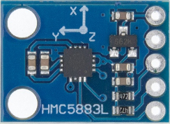
The HMC5883L is a digital compass module that utilizes a magnetometer to sense magnetic fields, allowing it to determine the Earth's magnetic headings. This small and low-cost module is commonly used in navigation systems for drones, robotics, and handheld compasses. Its ability to provide precise heading information makes it an essential component in orientation and position detection applications.

Explore Projects Built with HMC5883L compass

Use Cirkit Designer to design, explore, and prototype these projects online. Some projects support real-time simulation. Click "Open Project" to start designing instantly!
Arduino Uno R3 and HMC5883L Compass Interface
Image of Magnometer: A project utilizing HMC5883L compass in a practical application
This circuit connects an HMC5883L compass module to an Arduino Uno R3 for the purpose of reading magnetic field data. The Arduino is programmed to initialize the compass module, continuously read its X, Y, and Z magnetometer data, and output the readings to the Serial Monitor. The compass module is interfaced with the Arduino via I2C communication, using the SDA and SCL lines, and powered through the Arduino's VIN pin.
Cirkit Designer LogoOpen Project in Cirkit Designer
Raspberry Pi Pico-Based Bluetooth Compass
Image of sat_dish: compass-intro: A project utilizing HMC5883L compass in a practical application
This circuit features a Raspberry Pi Pico microcontroller interfaced with an HC-05 Bluetooth module and an HMC5883L digital compass. The Pico's GPIO pins are configured for serial communication with the HC-05 (TX/RX) and I2C communication with the HMC5883L (SCL/SDA). The circuit is likely designed for wireless data transmission of compass readings.
Cirkit Designer LogoOpen Project in Cirkit Designer
Raspberry Pi Pico-Based Navigation Assistant with Bluetooth and GPS
Image of sat_dish: compass example: A project utilizing HMC5883L compass in a practical application
This circuit features a Raspberry Pi Pico microcontroller interfaced with an HC-05 Bluetooth module for wireless communication, an HMC5883L compass module for magnetic field measurement, and a GPS NEO 6M module for location tracking. The Pico is configured to communicate with the HC-05 via serial connection (TX/RX), with the compass module via I2C (SCL/SDA), and with the GPS module via serial (TX/RX). Common power (VCC) and ground (GND) lines are shared among all modules, indicating a unified power system.
Cirkit Designer LogoOpen Project in Cirkit Designer
Arduino Nano-Based Portable GSM-GPS Navigator with Compass and Stepper Motor Control
Image of Compass: A project utilizing HMC5883L compass in a practical application
This circuit features an Arduino Nano microcontroller coordinating communication, navigation, and motion control functions. It includes modules for GSM, GPS, and digital compass capabilities, as well as a stepper motor for precise movement, all powered by a LiPo battery with voltage regulation.
Cirkit Designer LogoOpen Project in Cirkit Designer

Explore Projects Built with HMC5883L compass

Use Cirkit Designer to design, explore, and prototype these projects online. Some projects support real-time simulation. Click "Open Project" to start designing instantly!
Image of Magnometer: A project utilizing HMC5883L compass in a practical application
Arduino Uno R3 and HMC5883L Compass Interface
This circuit connects an HMC5883L compass module to an Arduino Uno R3 for the purpose of reading magnetic field data. The Arduino is programmed to initialize the compass module, continuously read its X, Y, and Z magnetometer data, and output the readings to the Serial Monitor. The compass module is interfaced with the Arduino via I2C communication, using the SDA and SCL lines, and powered through the Arduino's VIN pin.
Cirkit Designer LogoOpen Project in Cirkit Designer
Image of sat_dish: compass-intro: A project utilizing HMC5883L compass in a practical application
Raspberry Pi Pico-Based Bluetooth Compass
This circuit features a Raspberry Pi Pico microcontroller interfaced with an HC-05 Bluetooth module and an HMC5883L digital compass. The Pico's GPIO pins are configured for serial communication with the HC-05 (TX/RX) and I2C communication with the HMC5883L (SCL/SDA). The circuit is likely designed for wireless data transmission of compass readings.
Cirkit Designer LogoOpen Project in Cirkit Designer
Image of sat_dish: compass example: A project utilizing HMC5883L compass in a practical application
Raspberry Pi Pico-Based Navigation Assistant with Bluetooth and GPS
This circuit features a Raspberry Pi Pico microcontroller interfaced with an HC-05 Bluetooth module for wireless communication, an HMC5883L compass module for magnetic field measurement, and a GPS NEO 6M module for location tracking. The Pico is configured to communicate with the HC-05 via serial connection (TX/RX), with the compass module via I2C (SCL/SDA), and with the GPS module via serial (TX/RX). Common power (VCC) and ground (GND) lines are shared among all modules, indicating a unified power system.
Cirkit Designer LogoOpen Project in Cirkit Designer
Image of Compass: A project utilizing HMC5883L compass in a practical application
Arduino Nano-Based Portable GSM-GPS Navigator with Compass and Stepper Motor Control
This circuit features an Arduino Nano microcontroller coordinating communication, navigation, and motion control functions. It includes modules for GSM, GPS, and digital compass capabilities, as well as a stepper motor for precise movement, all powered by a LiPo battery with voltage regulation.
Cirkit Designer LogoOpen Project in Cirkit Designer

Technical Specifications

Key Technical Details

  • Supply Voltage (Vdd): 2.16V to 3.6V
  • Input Voltage (Vi): -0.3V to Vdd +0.3V
  • Measuring Range: ±1.3-8 Gauss
  • Resolution: 5 milli-Gauss
  • Communication: I2C (up to 400kHz)
  • Operating Temperature: -30°C to +85°C

Pin Configuration and Descriptions

Pin Number Name Description
1 VCC Power supply (2.16V to 3.6V)
2 GND Ground
3 SCL Serial Clock Line for I2C
4 SDA Serial Data Line for I2C
5 DRDY Data Ready (optional, active low)

Usage Instructions

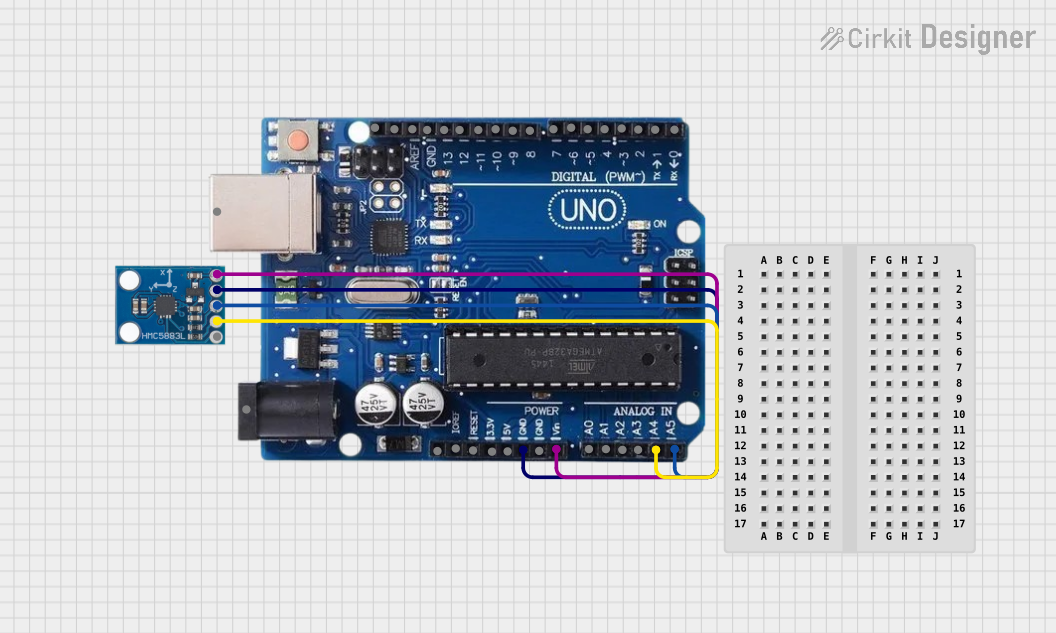
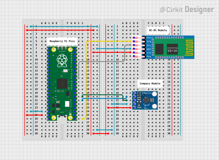
Integration with a Circuit

To use the HMC5883L in a circuit:

  1. Connect VCC to a 2.16V to 3.6V power supply.
  2. Connect GND to the ground of the power supply.
  3. Connect SCL to the I2C clock line.
  4. Connect SDA to the I2C data line.
  5. (Optional) Connect DRDY to a digital input pin if you wish to use the data ready feature.

Best Practices

  • Use pull-up resistors on the I2C lines (SCL and SDA).
  • Keep the power supply stable and within the specified range.
  • Place the module away from magnetic fields created by other electronic components.
  • Calibrate the compass for accurate readings in its final position within the application.

Example Code for Arduino UNO

#include <Wire.h>

// HMC5883L I2C address is 0x1E
#define Addr 0x1E

void setup() {
  // Initialise I2C communication as MASTER
  Wire.begin();
  // Initialise serial communication, set baud rate = 9600
  Serial.begin(9600);
  
  // Configure the HMC5883L
  Wire.beginTransmission(Addr);
  // Select mode register
  Wire.write(0x02);
  // Continuous measurement mode
  Wire.write(0x00);
  Wire.endTransmission();
  delay(300);
}

void loop() {
  int data[6];
  
  // Start I2C Transmission
  Wire.beginTransmission(Addr);
  // Select data register
  Wire.write(0x03);
  Wire.endTransmission();
  
  // Request 6 bytes of data
  Wire.requestFrom(Addr, 6);
  
  // Read 6 bytes of data
  // xMag msb, xMag lsb, zMag msb, zMag lsb, yMag msb, yMag lsb
  if (Wire.available() == 6) {
    data[0] = Wire.read() << 8;
    data[0] |= Wire.read();
    data[1] = Wire.read() << 8;
    data[1] |= Wire.read();
    data[2] = Wire.read() << 8;
    data[2] |= Wire.read();
  }
  
  // Convert the data
  int xMag = data[0];
  int zMag = data[1];
  int yMag = data[2];
  
  // Output data to serial monitor
  Serial.print("Magnetic field in X-Axis: ");
  Serial.println(xMag);
  Serial.print("Magnetic field in Z-Axis: ");
  Serial.println(zMag);
  Serial.print("Magnetic field in Y-Axis: ");
  Serial.println(yMag);
  
  delay(500);
}

Troubleshooting and FAQs

Common Issues

  • Inaccurate Readings: Ensure that the compass is calibrated and that there are no nearby magnetic sources affecting the readings.
  • No Data on I2C: Check the connections and ensure pull-up resistors are in place on the SCL and SDA lines.
  • Intermittent Communication: Ensure that the power supply is stable and within the specified voltage range.

FAQs

Q: How do I calibrate the HMC5883L? A: Calibration typically involves rotating the compass in all three axes and using software to find the calibration constants.

Q: Can the HMC5883L work with 5V systems? A: Directly connecting to a 5V system may damage the module. Use a level shifter or voltage divider for compatibility with 5V systems.

Q: How can I check if the HMC5883L is functioning properly? A: Run the example code provided and check the serial monitor for changing magnetic field values as you rotate the sensor.

Q: What is the purpose of the DRDY pin? A: The DRDY pin is an optional feature that signals when new data is available for reading, which can be useful for power-saving strategies or synchronizing readings.

Remember to always consult the HMC5883L datasheet for the most detailed and specific information regarding the operation and specifications of the component.