How to Use Victron Battery Charger 12/30: Examples, Pinouts, and Specs
Introduction
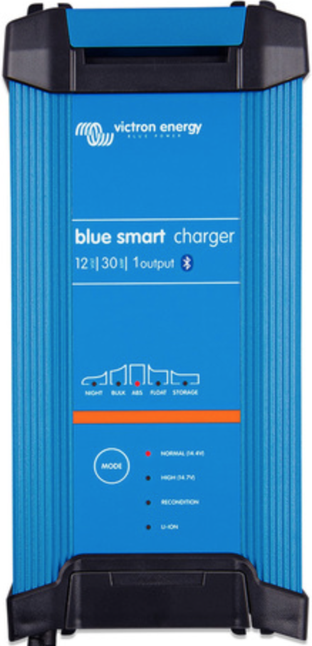
The Victron Battery Charger 12/30 is a high-quality, versatile charger designed for 12V batteries. With a maximum charging current of 30A, it is suitable for a wide range of applications, including automotive, marine, and off-grid power systems. This charger incorporates advanced charging algorithms to ensure optimal battery performance and longevity. It supports various battery chemistries, such as lead-acid (AGM, GEL) and lithium-ion, making it a reliable choice for diverse energy storage needs.
Explore Projects Built with Victron Battery Charger 12/30

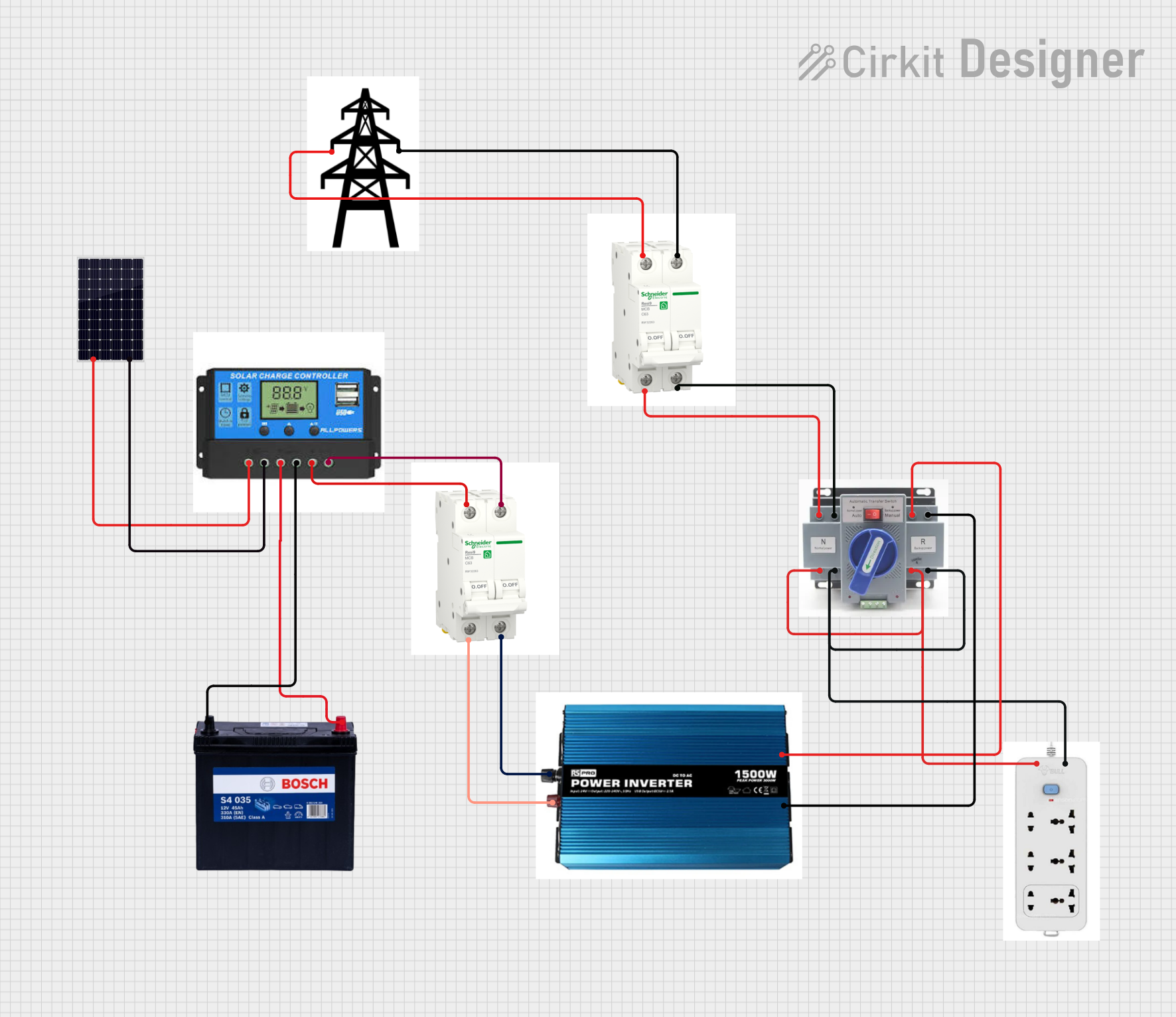
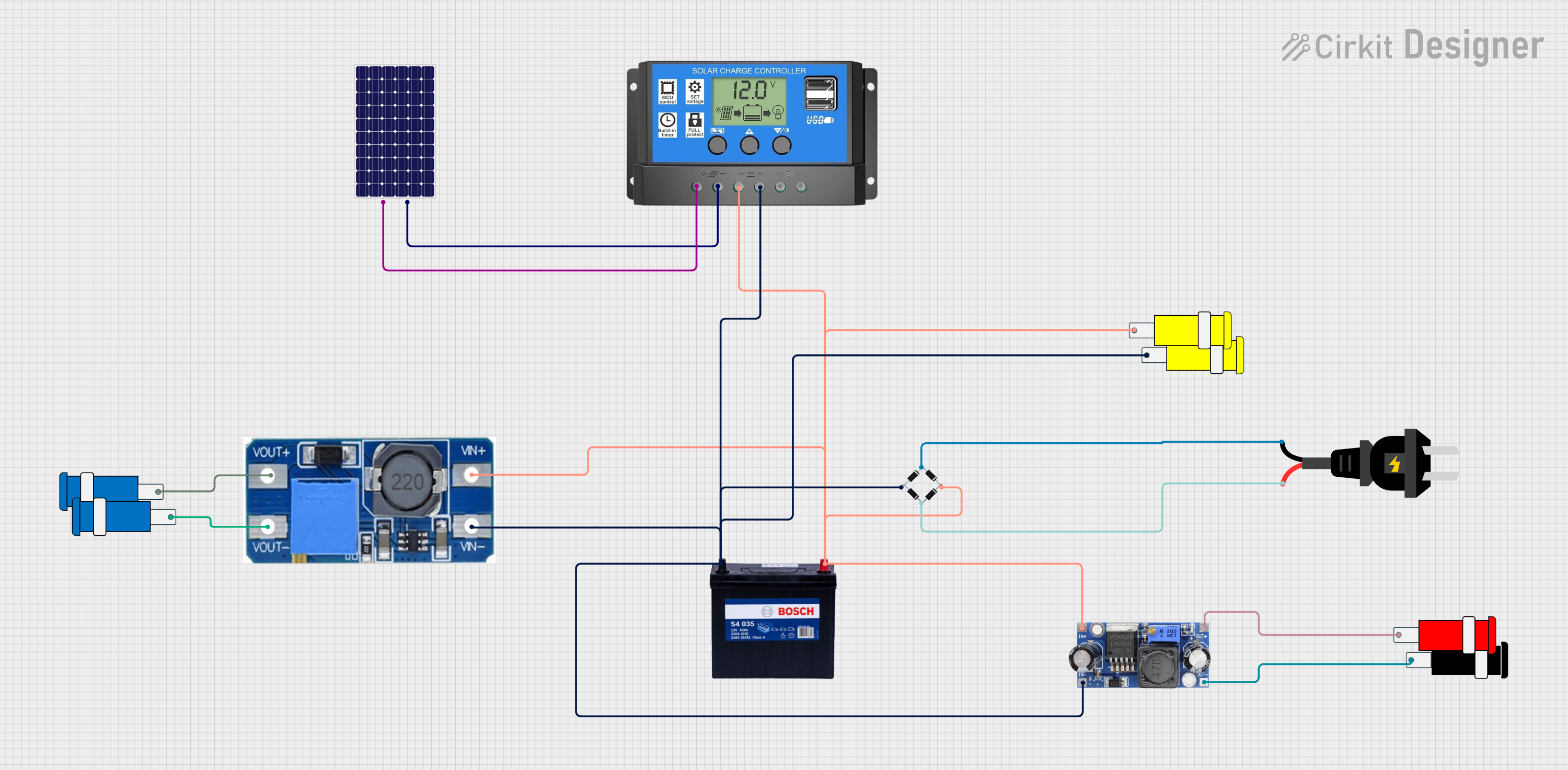

Explore Projects Built with Victron Battery Charger 12/30
Common Applications
- Charging 12V batteries in vehicles, boats, and RVs
- Off-grid solar power systems
- Backup power systems for homes and businesses
- Industrial battery maintenance
Technical Specifications
Key Technical Details
| Parameter | Specification |
|---|---|
| Input Voltage Range | 90-265V AC, 45-65Hz |
| Output Voltage | 12V DC |
| Maximum Charging Current | 30A |
| Battery Types Supported | Lead-acid (AGM, GEL), Lithium-ion |
| Charging Algorithm | Adaptive 4-stage (bulk, absorption, float, storage) |
| Efficiency | Up to 94% |
| Operating Temperature | -20°C to +50°C |
| Protection Features | Over-temperature, short-circuit, reverse polarity |
Pin Configuration and Descriptions
The Victron Battery Charger 12/30 does not have traditional pins but features the following key connections:
| Connection Point | Description |
|---|---|
| AC Input | Connects to the mains power supply (90-265V AC). |
| DC Output (+) | Positive terminal for connecting to the battery. |
| DC Output (-) | Negative terminal for connecting to the battery. |
| Remote On/Off Terminal | Allows remote control of the charger. |
| Temperature Sensor Port | For connecting an optional temperature sensor. |
| CAN Bus Port | For communication with Victron monitoring systems. |
Usage Instructions
How to Use the Victron Battery Charger 12/30
Connect the Charger to the Battery:
- Ensure the charger is powered off before making connections.
- Connect the positive DC output terminal to the positive terminal of the battery.
- Connect the negative DC output terminal to the negative terminal of the battery.
Connect the Charger to AC Power:
- Plug the AC input cable into a mains power outlet (90-265V AC).
- Ensure the outlet provides a stable power supply within the specified range.
Select the Battery Type:
- Use the charger’s interface or a compatible Victron monitoring system to select the appropriate battery type (e.g., AGM, GEL, Lithium-ion).
Start Charging:
- Turn on the charger using the power switch or remote on/off terminal.
- The charger will automatically detect the battery’s state of charge and apply the appropriate charging stage.
Monitor Charging:
- Use the built-in LED indicators or a Victron monitoring system to track the charging progress.
- Once the battery is fully charged, the charger will switch to float mode to maintain the charge.
Important Considerations and Best Practices
- Battery Compatibility: Ensure the battery type and capacity are compatible with the charger’s specifications.
- Ventilation: Place the charger in a well-ventilated area to prevent overheating.
- Temperature Sensor: Use the optional temperature sensor for precise charging in extreme temperature conditions.
- Safety Precautions: Avoid short-circuiting the terminals and ensure proper polarity when connecting the battery.
Arduino Integration
While the Victron Battery Charger 12/30 is not directly designed for Arduino integration, you can monitor its status using a Victron CAN Bus interface and an Arduino-compatible CAN Bus module. Below is an example code snippet for reading data from the charger via CAN Bus:
#include <SPI.h>
#include <mcp_can.h>

// Define CAN Bus module pins
#define CAN_CS_PIN 10  // Chip Select pin for the CAN module
#define CAN_INT_PIN 2  // Interrupt pin for the CAN module

MCP_CAN CAN(CAN_CS_PIN);  // Create CAN object

void setup() {
  Serial.begin(9600);  // Initialize serial communication
  while (!Serial);

  // Initialize CAN Bus at 500 kbps
  if (CAN.begin(MCP_ANY, 500000, MCP_8MHZ) == CAN_OK) {
    Serial.println("CAN Bus initialized successfully!");
  } else {
    Serial.println("Error initializing CAN Bus.");
    while (1);
  }

  CAN.setMode(MCP_NORMAL);  // Set CAN Bus to normal mode
}

void loop() {
  // Check for incoming CAN messages
  if (CAN.checkReceive() == CAN_MSGAVAIL) {
    long unsigned int id;
    unsigned char len;
    unsigned char buf[8];

    // Read the CAN message
    CAN.readMsgBuf(&id, &len, buf);

    // Print the message ID and data
    Serial.print("Message ID: 0x");
    Serial.println(id, HEX);
    Serial.print("Data: ");
    for (int i = 0; i < len; i++) {
      Serial.print(buf[i], HEX);
      Serial.print(" ");
    }
    Serial.println();
  }
}
Note: This code assumes you are using an MCP2515-based CAN Bus module. Modify the code as needed for your specific hardware setup.
Troubleshooting and FAQs
Common Issues and Solutions
Charger Does Not Turn On:
- Ensure the AC power supply is within the specified range (90-265V AC).
- Check the power cable and connections for damage or loose connections.
Battery Not Charging:
- Verify the battery type is correctly selected.
- Check the DC output connections for proper polarity and secure contact.
- Ensure the battery is not damaged or excessively discharged.
Overheating:
- Ensure the charger is placed in a well-ventilated area.
- Check for obstructions around the cooling vents.
LED Indicators Not Working:
- Inspect the charger for physical damage.
- Verify the AC power supply and connections.
Frequently Asked Questions
Q: Can I use this charger for a 24V battery?
A: No, the Victron Battery Charger 12/30 is specifically designed for 12V batteries. Using it with a 24V battery may damage the charger or the battery.
Q: Is the charger waterproof?
A: No, the charger is not waterproof. It should be used in a dry, indoor environment or a weather-protected enclosure.
Q: Can I leave the charger connected to the battery indefinitely?
A: Yes, the charger’s adaptive charging algorithm ensures safe long-term maintenance of the battery by switching to float mode once the battery is fully charged.
Q: How do I update the charger’s firmware?
A: Firmware updates can be performed using a Victron interface device, such as the VE.Direct cable, and the VictronConnect app.
Q: What is the warranty period for this charger?
A: The warranty period for Victron products, including the Battery Charger 12/30, is typically 5 years. Refer to the manufacturer’s documentation for specific terms and conditions.