
How to Use BUTTONPAD-2X2: Examples, Pinouts, and Specs
 Design with BUTTONPAD-2X2 in Cirkit Designer
Introduction
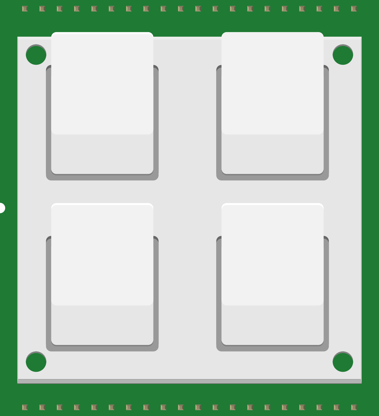
The BUTTONPAD-2X2 (Manufacturer Part ID: COM-07835) is a compact 2x2 matrix button pad manufactured by SparkFun Electronics. It features four tactile buttons arranged in a 2x2 grid, making it ideal for applications requiring simple and intuitive user input. The button pad is designed for easy integration into projects, offering a straightforward interface for controlling devices or triggering actions.
Explore Projects Built with BUTTONPAD-2X2
 Open Project in Cirkit Designer
 Open Project in Cirkit Designer
 Open Project in Cirkit Designer
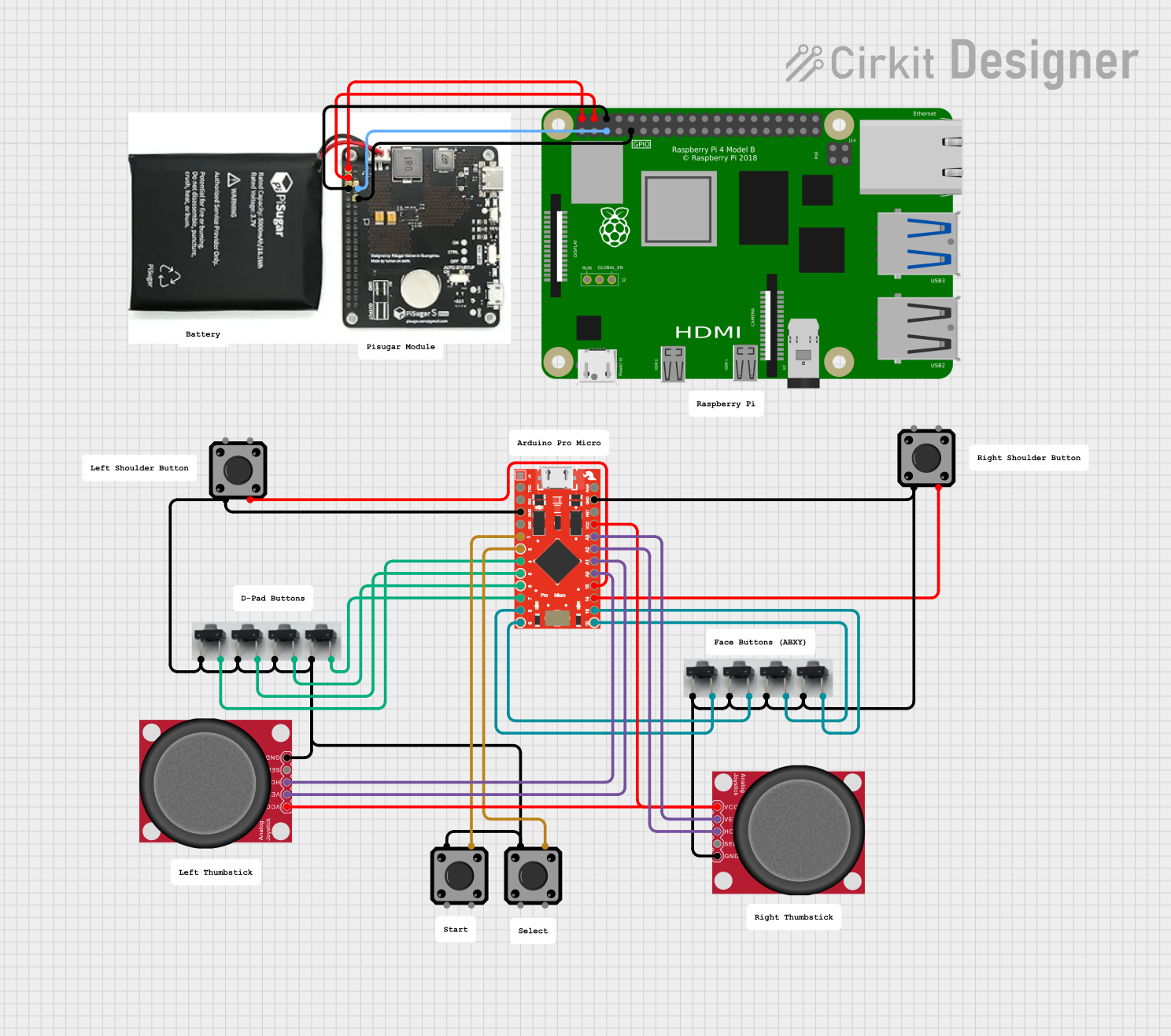 Open Project in Cirkit Designer
Explore Projects Built with BUTTONPAD-2X2
Open Project in Cirkit DesignerOpen Project in Cirkit DesignerOpen Project in Cirkit DesignerOpen Project in Cirkit DesignerCommon Applications
- User input for microcontroller-based projects
- Control panels for robotics or automation systems
- Menu navigation in embedded systems
- Gaming controllers or custom keypads
- Prototyping and DIY electronics projects
Technical Specifications
The BUTTONPAD-2X2 is designed for ease of use and compatibility with a wide range of microcontrollers and systems. Below are its key technical details:
Key Specifications
| Parameter | Value |
|---|---|
| Manufacturer | SparkFun Electronics |
| Part Number | COM-07835 |
| Button Configuration | 2x2 matrix (4 buttons total) |
| Operating Voltage | 3.3V to 5V |
| Button Type | Tactile momentary switches |
| Dimensions | 1.7" x 1.7" (43mm x 43mm) |
| Mounting Style | PCB mount |
| Connector Type | Solder pads or pin headers |
Pin Configuration
The BUTTONPAD-2X2 uses a 2x2 matrix configuration, requiring four connections to interface with the buttons. The pins are typically labeled as follows:
| Pin Name | Description |
|---|---|
| ROW1 | Row 1 of the button matrix |
| ROW2 | Row 2 of the button matrix |
| COL1 | Column 1 of the button matrix |
| COL2 | Column 2 of the button matrix |
Each button in the matrix is connected to a unique combination of one row and one column. For example:
- Button 1: ROW1 + COL1
- Button 2: ROW1 + COL2
- Button 3: ROW2 + COL1
- Button 4: ROW2 + COL2
Usage Instructions
How to Use the BUTTONPAD-2X2 in a Circuit
- Connect the Pins: Solder wires or pin headers to the ROW and COL pads on the button pad. Connect these to the corresponding GPIO pins on your microcontroller.
- Enable Pull-Up Resistors: Configure the microcontroller's GPIO pins with internal pull-up resistors or use external pull-up resistors to ensure stable button readings.
- Scan the Matrix: Use a matrix scanning algorithm to detect button presses. This involves setting one row LOW at a time and checking the state of the columns.
Example Circuit
Below is an example of how to connect the BUTTONPAD-2X2 to an Arduino UNO:
- ROW1 → Digital Pin 2
- ROW2 → Digital Pin 3
- COL1 → Digital Pin 4
- COL2 → Digital Pin 5
Example Arduino Code
The following Arduino sketch demonstrates how to read button presses from the BUTTONPAD-2X2:
// Define pin connections for the button pad
const int rowPins[2] = {2, 3}; // ROW1 and ROW2
const int colPins[2] = {4, 5}; // COL1 and COL2

void setup() {
  // Initialize row pins as outputs
  for (int i = 0; i < 2; i++) {
    pinMode(rowPins[i], OUTPUT);
    digitalWrite(rowPins[i], HIGH); // Set rows HIGH by default
  }

  // Initialize column pins as inputs with pull-up resistors
  for (int i = 0; i < 2; i++) {
    pinMode(colPins[i], INPUT_PULLUP);
  }

  Serial.begin(9600); // Start serial communication
}

void loop() {
  // Scan each row
  for (int row = 0; row < 2; row++) {
    digitalWrite(rowPins[row], LOW); // Activate the current row

    // Check each column for a button press
    for (int col = 0; col < 2; col++) {
      if (digitalRead(colPins[col]) == LOW) {
        // Button press detected
        Serial.print("Button Pressed: Row ");
        Serial.print(row + 1);
        Serial.print(", Column ");
        Serial.println(col + 1);
      }
    }

    digitalWrite(rowPins[row], HIGH); // Deactivate the current row
  }

  delay(100); // Small delay to debounce buttons
}
Important Considerations
- Debouncing: Mechanical buttons can produce noise when pressed or released. Use software debouncing (e.g., a small delay) or a hardware debouncing circuit to ensure reliable readings.
- Voltage Levels: Ensure the operating voltage of the BUTTONPAD-2X2 matches the logic level of your microcontroller (3.3V or 5V).
- Matrix Scanning Speed: Adjust the scanning speed to balance responsiveness and stability.
Troubleshooting and FAQs
Common Issues
Buttons Not Responding
- Cause: Incorrect wiring or loose connections.
- Solution: Double-check the connections between the button pad and the microcontroller. Ensure all solder joints are secure.
Multiple Buttons Detected at Once
- Cause: Ghosting effect in the matrix.
- Solution: Use diodes in series with each button to prevent ghosting, or limit simultaneous button presses.
Unstable Readings
- Cause: Button bounce or insufficient pull-up resistors.
- Solution: Implement software debouncing and verify the pull-up resistor configuration.
FAQs
Q: Can I use the BUTTONPAD-2X2 with a Raspberry Pi?
A: Yes, the BUTTONPAD-2X2 can be used with a Raspberry Pi. Connect the ROW and COL pins to GPIO pins on the Raspberry Pi and use a Python library like RPi.GPIO to scan the matrix.
Q: How many BUTTONPAD-2X2 modules can I use in a single project?
A: The number of modules depends on the available GPIO pins on your microcontroller. Each module requires four GPIO pins.
Q: Is the BUTTONPAD-2X2 waterproof?
A: No, the BUTTONPAD-2X2 is not waterproof. Avoid exposing it to moisture or liquids.
This concludes the documentation for the BUTTONPAD-2X2. For further assistance, refer to SparkFun's official resources or community forums.