How to Use NC96: Examples, Pinouts, and Specs
Introduction
The NC96 is a versatile integrated circuit (IC) designed for a wide range of electronic applications. It is commonly used in signal processing, amplification, and control systems, making it a popular choice for both hobbyists and professionals. Its compact design and multifunctional capabilities allow it to be integrated into various devices, including audio systems, communication equipment, and industrial control systems.
Explore Projects Built with NC96


Explore Projects Built with NC96
Common Applications
- Signal amplification in audio and communication systems
- Control circuits in industrial automation
- Signal processing in embedded systems
- General-purpose electronic projects
Technical Specifications
The NC96 is designed to operate efficiently under a variety of conditions. Below are its key technical specifications:
| Parameter | Value |
|---|---|
| Supply Voltage (Vcc) | 3.3V to 12V |
| Operating Current | 10 mA (typical) |
| Maximum Output Current | 50 mA |
| Operating Temperature | -40°C to +85°C |
| Package Type | DIP-8 or SOIC-8 |
| Frequency Range | DC to 1 MHz |
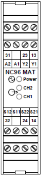
Pin Configuration
The NC96 features an 8-pin configuration. The table below describes each pin:
| Pin Number | Pin Name | Description |
|---|---|---|
| 1 | Vcc | Positive power supply input |
| 2 | IN1 | Input signal 1 |
| 3 | IN2 | Input signal 2 |
| 4 | GND | Ground (0V reference) |
| 5 | OUT1 | Output signal 1 |
| 6 | OUT2 | Output signal 2 |
| 7 | CTRL | Control pin for enabling/disabling functionality |
| 8 | NC | No connection (reserved for future use) |
Usage Instructions
How to Use the NC96 in a Circuit
- Power Supply: Connect the Vcc pin (Pin 1) to a stable power source within the range of 3.3V to 12V. Connect the GND pin (Pin 4) to the ground of the circuit.
- Input Signals: Feed the input signals to IN1 (Pin 2) and IN2 (Pin 3). Ensure the input signals are within the acceptable voltage range of the IC.
- Output Signals: The processed signals will be available at OUT1 (Pin 5) and OUT2 (Pin 6). Connect these pins to the desired load or circuit.
- Control Pin: Use the CTRL pin (Pin 7) to enable or disable the IC's functionality. A HIGH signal enables the IC, while a LOW signal disables it.
Important Considerations
- Decoupling Capacitors: Place a 0.1 µF ceramic capacitor close to the Vcc pin to filter out noise and stabilize the power supply.
- Signal Integrity: Ensure that input signals are clean and within the specified frequency range to avoid distortion.
- Thermal Management: Operate the IC within the recommended temperature range to prevent overheating.
Example: Connecting NC96 to an Arduino UNO
The NC96 can be easily interfaced with an Arduino UNO for signal processing applications. Below is an example code snippet:
// Example: Using NC96 with Arduino UNO
// This code demonstrates how to enable the NC96 and process input signals.

// Define pin connections
const int ctrlPin = 7;  // Arduino pin connected to NC96 CTRL pin
const int inputPin = A0; // Analog input pin for signal monitoring
const int outputPin = 9; // PWM output pin connected to NC96 OUT1

void setup() {
  pinMode(ctrlPin, OUTPUT);  // Set CTRL pin as output
  pinMode(outputPin, OUTPUT); // Set output pin as output
  digitalWrite(ctrlPin, HIGH); // Enable the NC96
  Serial.begin(9600); // Initialize serial communication
}

void loop() {
  int inputSignal = analogRead(inputPin); // Read input signal
  int outputSignal = map(inputSignal, 0, 1023, 0, 255);
  // Map input signal to PWM range

  analogWrite(outputPin, outputSignal); // Output processed signal
  Serial.println(outputSignal); // Print output signal for debugging
  delay(10); // Small delay for stability
}
Troubleshooting and FAQs
Common Issues
No Output Signal
- Cause: The CTRL pin is not enabled.
- Solution: Ensure the CTRL pin is set HIGH to enable the IC.
Distorted Output
- Cause: Input signal exceeds the specified frequency range.
- Solution: Verify that the input signal is within the DC to 1 MHz range.
Overheating
- Cause: Operating the IC beyond its maximum current or voltage ratings.
- Solution: Ensure the supply voltage and output current are within the specified limits.
Noise in Output
- Cause: Insufficient decoupling on the power supply.
- Solution: Add a 0.1 µF capacitor near the Vcc pin to filter noise.
FAQs
Q1: Can the NC96 handle AC signals?
A1: Yes, the NC96 can process AC signals as long as they are within the specified frequency range and voltage levels.
Q2: What happens if the CTRL pin is left floating?
A2: Leaving the CTRL pin floating may result in unpredictable behavior. It is recommended to connect it to a defined HIGH or LOW state.
Q3: Can I use the NC96 with a 5V power supply?
A3: Yes, the NC96 operates within a supply voltage range of 3.3V to 12V, so a 5V power supply is suitable.
Q4: Is the NC96 suitable for high-frequency applications?
A4: The NC96 supports frequencies up to 1 MHz, making it suitable for low to mid-frequency applications. For higher frequencies, consider a specialized IC.