How to Use Adafruit ANO Rotary Navigation Encoder Breakout: Examples, Pinouts, and Specs
Introduction
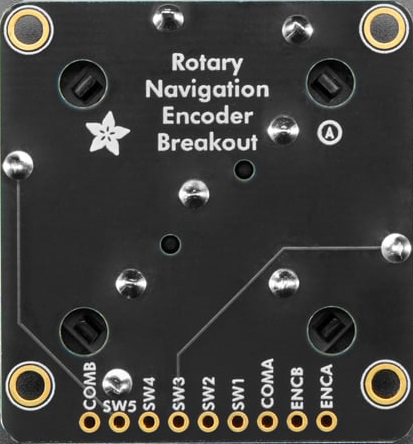
The Adafruit ANO Rotary Navigation Encoder Breakout is a compact and versatile rotary encoder module designed for easy integration into electronic projects. It features a high-resolution rotary encoder for precise position feedback and a built-in push button for additional input functionality. This breakout board is ideal for creating user interfaces, menu navigation systems, and control panels in a wide range of applications.
Explore Projects Built with Adafruit ANO Rotary Navigation Encoder Breakout
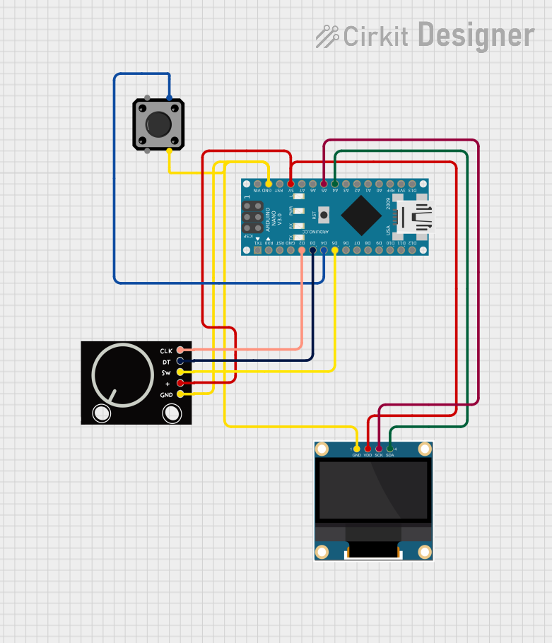
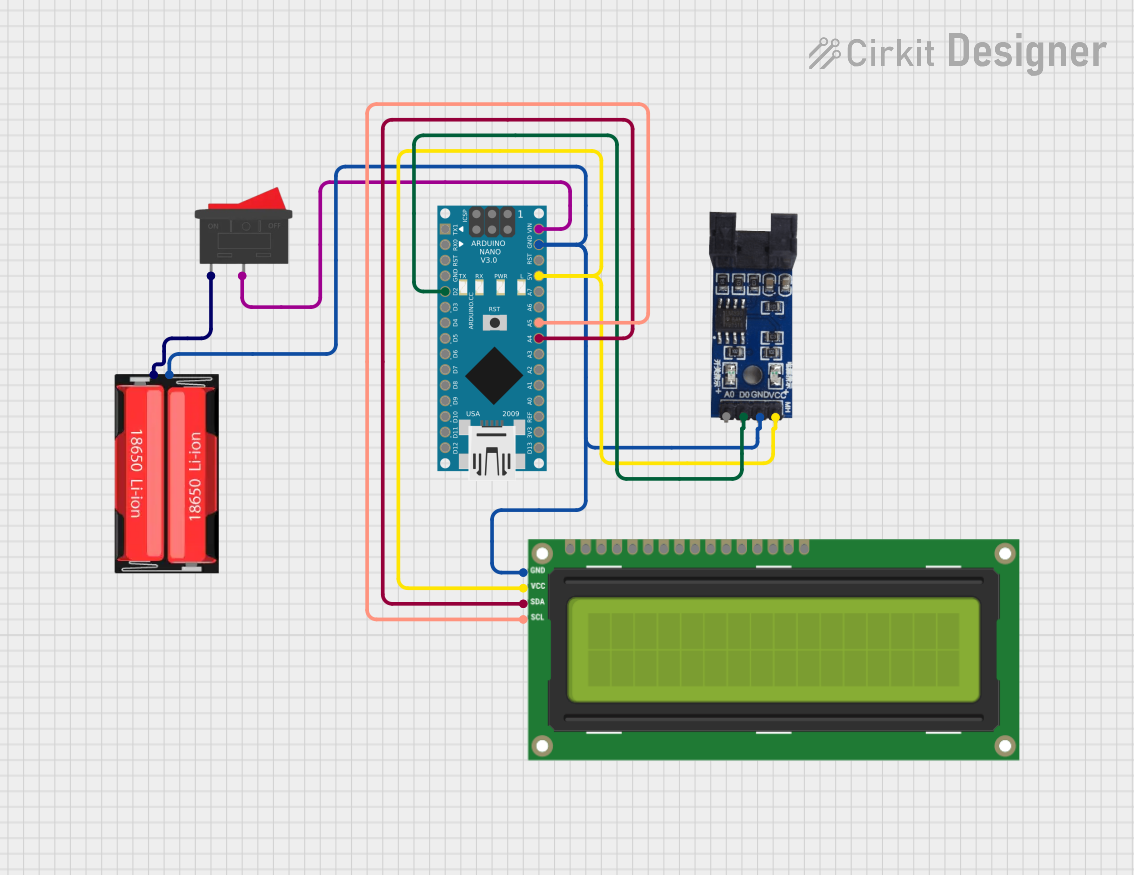
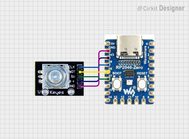
Explore Projects Built with Adafruit ANO Rotary Navigation Encoder Breakout
Common Applications and Use Cases
- User interface navigation for embedded systems
- Menu selection and scrolling in control panels
- Volume or parameter adjustment in audio and video equipment
- Robotics and automation control
- DIY electronics projects requiring precise input control
Technical Specifications
The Adafruit ANO Rotary Navigation Encoder Breakout is designed for ease of use and compatibility with microcontrollers like Arduino. Below are its key technical details:
Key Technical Details
- Operating Voltage: 3.3V or 5V (logic level compatible)
- Interface: Digital (rotary encoder and push button)
- Rotary Encoder Resolution: 24 pulses per revolution (PPR)
- Push Button: Integrated momentary switch
- Dimensions: 20mm x 20mm (excluding pins)
- Mounting Holes: 2 x M2.5 for secure attachment
- Connector Type: 5-pin header (GND, VCC, SW, DT, CLK)
Pin Configuration and Descriptions
The breakout board has a 5-pin header for easy connection. Below is the pinout:
| Pin | Name | Description |
|---|---|---|
| 1 | GND | Ground connection for the module. |
| 2 | VCC | Power supply input (3.3V or 5V). |
| 3 | SW | Push button output (active LOW). |
| 4 | DT | Data pin for the rotary encoder (used for direction detection). |
| 5 | CLK | Clock pin for the rotary encoder (used for detecting rotation steps). |
Usage Instructions
The Adafruit ANO Rotary Navigation Encoder Breakout is straightforward to use in a circuit. Below are the steps and best practices for integrating it into your project.
How to Use the Component in a Circuit
- Connect the Power Supply:
- Connect the
VCCpin to the 3.3V or 5V power supply of your microcontroller. - Connect the
GNDpin to the ground of your circuit.
- Connect the
- Connect the Rotary Encoder Pins:
- Connect the
CLKandDTpins to two digital input pins on your microcontroller.
- Connect the
- Connect the Push Button:
- Connect the
SWpin to another digital input pin on your microcontroller.
- Connect the
- Add Pull-Up Resistors (if necessary):
- If your microcontroller does not have internal pull-up resistors, add external pull-up resistors (10kΩ) to the
SW,CLK, andDTpins.
- If your microcontroller does not have internal pull-up resistors, add external pull-up resistors (10kΩ) to the
Arduino Example Code
Below is an example Arduino sketch to read the rotary encoder and push button inputs:
// Define pin connections for the rotary encoder
#define CLK 2  // Clock pin connected to digital pin 2
#define DT 3   // Data pin connected to digital pin 3
#define SW 4   // Push button pin connected to digital pin 4

int lastStateCLK;  // Variable to store the previous state of the CLK pin
int currentStateCLK;  // Variable to store the current state of the CLK pin
int counter = 0;  // Counter to track the encoder position

void setup() {
  pinMode(CLK, INPUT);  // Set CLK pin as input
  pinMode(DT, INPUT);   // Set DT pin as input
  pinMode(SW, INPUT_PULLUP);  // Set SW pin as input with internal pull-up resistor

  // Read the initial state of the CLK pin
  lastStateCLK = digitalRead(CLK);

  // Initialize serial communication for debugging
  Serial.begin(9600);
}

void loop() {
  // Read the current state of the CLK pin
  currentStateCLK = digitalRead(CLK);

  // Check if the state of CLK has changed
  if (currentStateCLK != lastStateCLK) {
    // If the DT pin state matches the CLK state, the encoder is rotating clockwise
    if (digitalRead(DT) != currentStateCLK) {
      counter++;
    } else {
      // Otherwise, the encoder is rotating counterclockwise
      counter--;
    }

    // Print the current counter value to the serial monitor
    Serial.print("Position: ");
    Serial.println(counter);
  }

  // Update the last state of the CLK pin
  lastStateCLK = currentStateCLK;

  // Check if the push button is pressed
  if (digitalRead(SW) == LOW) {
    Serial.println("Button Pressed!");
    delay(200);  // Debounce delay
  }
}
Important Considerations and Best Practices
- Debouncing: Rotary encoders and push buttons may produce noise or false signals. Use software debouncing or hardware filters to ensure reliable operation.
- Power Supply: Ensure the module is powered with the correct voltage (3.3V or 5V) to avoid damage.
- Pull-Up Resistors: Use pull-up resistors for the
SW,CLK, andDTpins if your microcontroller does not have internal pull-ups. - Secure Mounting: Use the mounting holes to securely attach the breakout board to your project.
Troubleshooting and FAQs
Common Issues and Solutions
No Response from the Encoder:
- Verify all connections, especially the
CLKandDTpins. - Ensure the power supply voltage matches the module's requirements.
- Check for loose or broken wires.
- Verify all connections, especially the
Incorrect Direction Detection:
- Swap the
CLKandDTpin connections if the direction is reversed. - Ensure the code logic matches the encoder's behavior.
- Swap the
Push Button Not Working:
- Check the
SWpin connection and ensure it is configured as an input. - Verify the pull-up resistor is enabled (internal or external).
- Check the
Erratic or Noisy Signals:
- Add a small capacitor (e.g., 0.1µF) between the
CLKandDTpins and ground to filter noise. - Implement software debouncing in your code.
- Add a small capacitor (e.g., 0.1µF) between the
FAQs
Q: Can I use this module with a Raspberry Pi?
A: Yes, the Adafruit ANO Rotary Navigation Encoder Breakout is compatible with Raspberry Pi. Use GPIO pins for the CLK, DT, and SW connections, and ensure proper pull-up resistors are configured.
Q: What is the resolution of the rotary encoder?
A: The rotary encoder provides 24 pulses per revolution (PPR), allowing for precise position feedback.
Q: Can I use this module with 3.3V logic microcontrollers?
A: Yes, the module is compatible with both 3.3V and 5V logic levels.
Q: How do I debounce the push button?
A: You can use a software debounce routine (e.g., delay after detecting a button press) or add a hardware debounce circuit with a resistor and capacitor.
By following this documentation, you can effectively integrate the Adafruit ANO Rotary Navigation Encoder Breakout into your projects and troubleshoot any issues that arise.