How to Use Adafruit VL53L0X Time of Flight Distance Sensor: Examples, Pinouts, and Specs
Introduction
The Adafruit VL53L0X Time of Flight Distance Sensor is a state-of-the-art sensor that utilizes Time of Flight (ToF) technology to measure distances with high accuracy. It is capable of measuring distances up to 2 meters, making it an ideal choice for a wide range of applications, including robotics, user gesture recognition, and obstacle detection systems. The sensor operates by emitting a very short infrared laser pulse and then measuring the time it takes for the light to bounce back from an object. This technology allows for precise and reliable distance measurements, even in challenging environmental conditions.
Explore Projects Built with Adafruit VL53L0X Time of Flight Distance Sensor


Explore Projects Built with Adafruit VL53L0X Time of Flight Distance Sensor
Technical Specifications
Key Technical Details
- Operating Voltage: 2.6V to 5.5V
- Average Current Consumption: 10 to 20 mA
- Peak Current Consumption: 40 mA
- Maximum Range: Up to 2 meters
- Resolution: 1 mm
- Interface: I2C
- I2C Address: Default 0x29 (7-bit), adjustable to any 7-bit value
- Laser Wavelength: 940 nm (Infrared)
- Field of View: 25°
- Operating Temperature Range: -20°C to 70°C
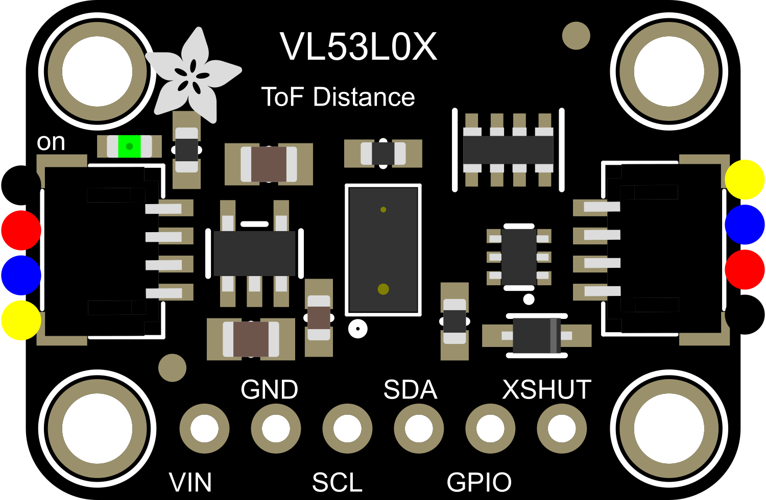
Pin Configuration and Descriptions
| Pin Name | Description |
|---|---|
| VIN | Power supply (2.6V to 5.5V) |
| GND | Ground |
| SCL | I2C clock line |
| SDA | I2C data line |
| GPIO1 | Interrupt output (active low) |
| XSHUT | Shutdown input (active low) |
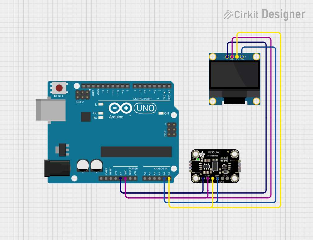
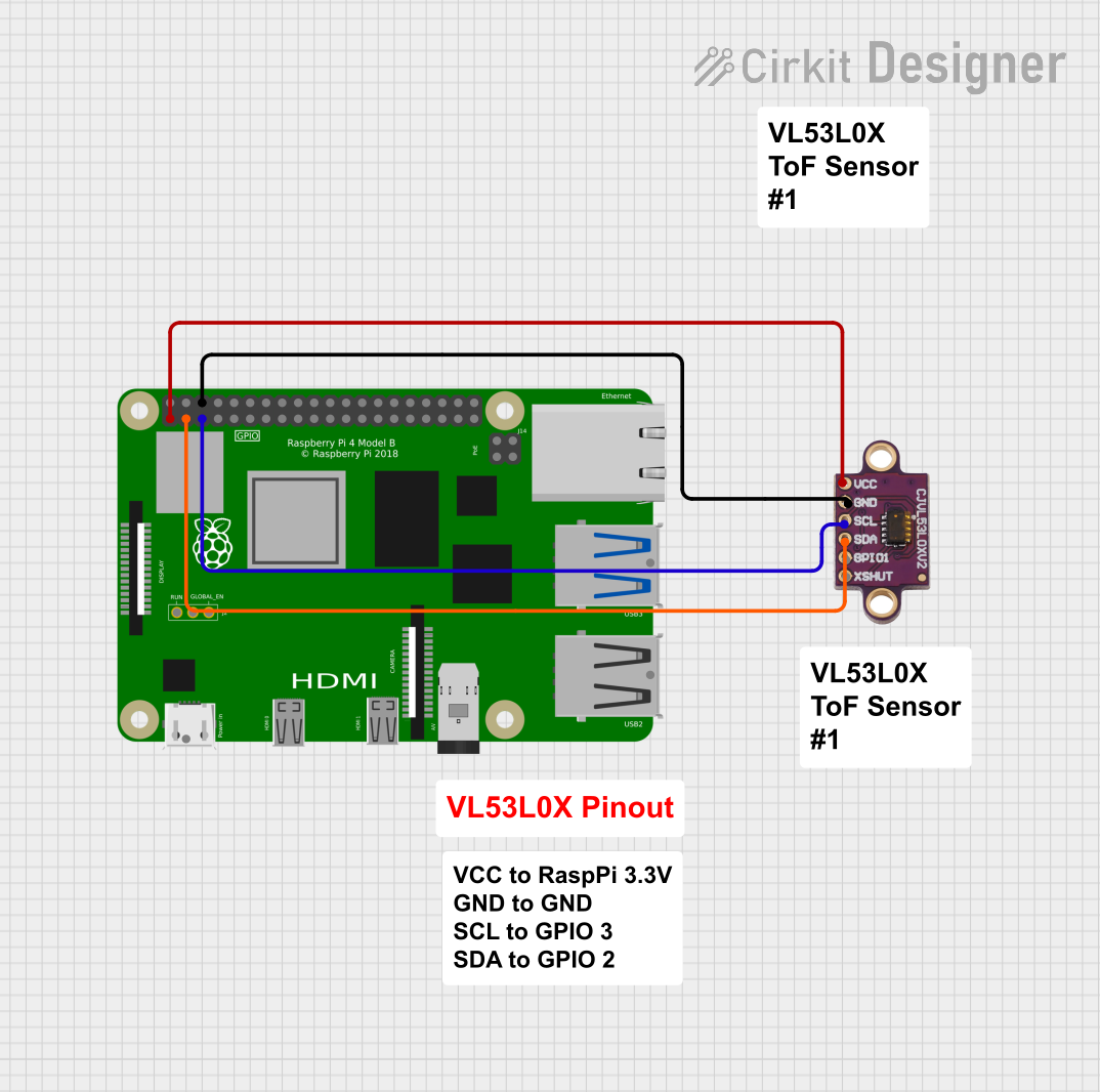
Usage Instructions
Integrating with a Circuit
To use the VL53L0X sensor in a circuit, follow these steps:
- Connect the VIN pin to a 2.6V to 5.5V power supply.
- Connect the GND pin to the ground of the power supply.
- Connect the SCL and SDA pins to the I2C clock and data lines, respectively.
- Optionally, connect the GPIO1 pin if interrupt functionality is required.
- Optionally, connect the XSHUT pin to a digital output if you need to control the power-down mode of the sensor.
Best Practices
- Ensure that the power supply is stable and within the specified voltage range.
- Use pull-up resistors on the I2C lines if they are not already present on the microcontroller board.
- Avoid exposing the sensor to direct sunlight or strong infrared sources to prevent measurement errors.
- Keep the sensor lens clean and free from obstructions.
Example Code for Arduino UNO
#include <Wire.h>
#include <Adafruit_VL53L0X.h>

Adafruit_VL53L0X lox = Adafruit_VL53L0X();

void setup() {
  Serial.begin(9600);

  // Wait for serial port to connect
  while (!Serial) { delay(1); }

  // Initialize I2C communication
  Wire.begin();

  // Initialize sensor with default settings
  if (!lox.begin()) {
    Serial.println(F("Failed to boot VL53L0X"));
    while(1);
  }
}

void loop() {
  VL53L0X_RangingMeasurementData_t measure;

  // Perform a ranging measurement
  lox.rangingTest(&measure, false); // pass 'true' for debug output

  if (measure.RangeStatus != 4) {  // If range status is valid
    Serial.print("Distance (mm): ");
    Serial.println(measure.RangeMilliMeter);
  } else {
    Serial.println("Out of range");
  }

  delay(100);
}
Troubleshooting and FAQs
Common Issues
- Sensor Not Responding: Ensure that the I2C connections are correct and that the sensor is powered.
- Inaccurate Readings: Check for obstructions in front of the sensor and avoid using it in direct sunlight.
- Intermittent Operation: Verify that the power supply is stable and within the specified voltage range.
Solutions and Tips
- If the sensor is not detected on the I2C bus, check the wiring and try scanning for the device with an I2C scanner sketch.
- For inaccurate readings, recalibrate the sensor if necessary and ensure that the lens is clean.
- If the sensor is behaving erratically, check for loose connections and ensure that the microcontroller's I2C pull-up resistors are correctly configured.
FAQs
Q: Can I change the I2C address of the sensor? A: Yes, the I2C address can be changed by writing to the I2C_Slave_Device_Address register.
Q: What is the maximum I2C speed the sensor supports? A: The VL53L0X supports I2C speeds up to 400 kHz (Fast Mode).
Q: Can the sensor measure distances beyond 2 meters? A: The sensor is optimized for distances up to 2 meters. Measurements beyond this range may be less accurate or unreliable.
Q: Is the sensor safe for eyes? A: Yes, the sensor uses a Class 1 laser which is safe for the eyes under all conditions of normal use.
For further assistance, consult the Adafruit VL53L0X datasheet and the manufacturer's technical support resources.