How to Use Power Transformer (120V to 24V): Examples, Pinouts, and Specs
Introduction
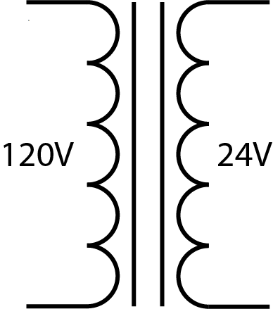
A power transformer is a critical component in electrical and electronic systems, used to convert alternating current (AC) power from one voltage level to another through electromagnetic induction. The 120V to 24V power transformer steps down the voltage from a standard US household voltage of 120 volts to a lower voltage of 24 volts, which is commonly required for various low-voltage applications such as control circuits, HVAC systems, and certain types of lighting.
Explore Projects Built with Power Transformer (120V to 24V)

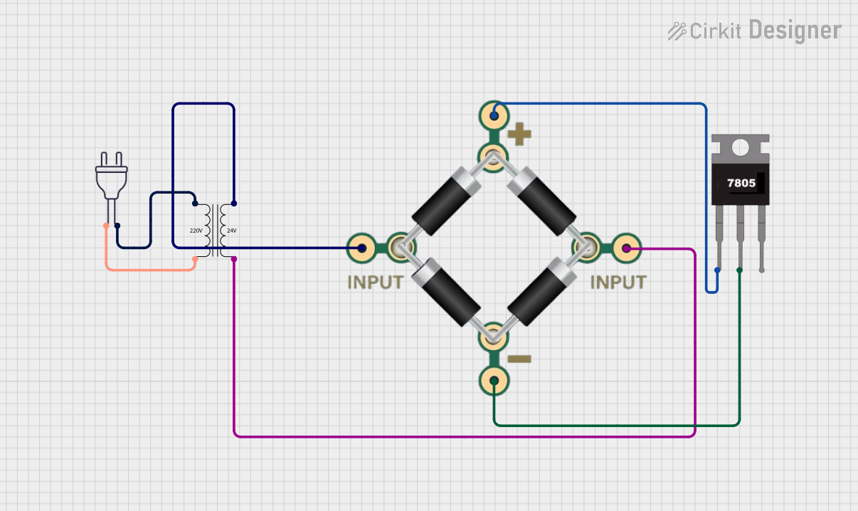

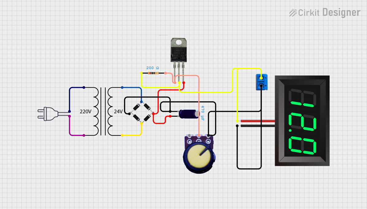
Explore Projects Built with Power Transformer (120V to 24V)
Common Applications and Use Cases
- HVAC control systems
- Industrial control panels
- Lighting systems
- Power supplies for electronic devices
- Safety circuits
Technical Specifications
Key Technical Details
- Input Voltage: 120V AC
- Output Voltage: 24V AC
- Frequency: 60Hz (standard in the US)
- Power Rating: Varies by model (expressed in VA - Volt-Ampere)
- Insulation Class: Typically Class B or higher
- Temperature Rise: Specified by manufacturer, often 40°C or 80°C
- Phase: Single-phase
Pin Configuration and Descriptions
| Pin Number | Description | Notes |
|---|---|---|
| 1 | Primary (Input) L1 | Connect to 120V AC Line |
| 2 | Primary (Input) N | Connect to Neutral |
| 3 | Secondary (Output) L2 | 24V AC output (Load) |
| 4 | Secondary (Output) N | 24V AC output (Neutral/Return) |
Note: The actual pin configuration may vary based on the transformer design and manufacturer. Always refer to the manufacturer's datasheet for exact details.
Usage Instructions
How to Use the Component in a Circuit
- Mounting: Secure the transformer to a stable surface using the provided mounting hardware.
- Wiring the Primary Side:
- Disconnect power before wiring.
- Connect the primary side (pins 1 and 2) to the 120V AC power source.
- Ensure proper grounding for safety.
- Wiring the Secondary Side:
- Connect the secondary side (pins 3 and 4) to the load that requires 24V AC.
- Use appropriate wire gauge based on the current rating.
Important Considerations and Best Practices
- Safety: Always follow local electrical codes and regulations.
- Isolation: Ensure the transformer provides electrical isolation between the primary and secondary circuits.
- Overload Protection: Use fuses or circuit breakers to protect against overcurrent conditions.
- Heat Dissipation: Allow for adequate ventilation around the transformer to prevent overheating.
- Grounding: Properly ground the transformer to prevent electrical shock hazards.
Troubleshooting and FAQs
Common Issues Users Might Face
- No Output Voltage: Check input connections, fuses, and circuit breakers.
- Overheating: Ensure the transformer is not exceeding its rated power capacity and has proper ventilation.
- Noise or Vibration: Verify that the transformer is securely mounted and that there are no loose parts.
Solutions and Tips for Troubleshooting
- Check Connections: Loose connections can cause failure or underperformance.
- Measure Input Voltage: Ensure the input voltage is within the specified range.
- Inspect for Damage: Physical damage can lead to malfunction. Replace if necessary.
FAQs
- Q: Can this transformer be used with a different frequency?
- A: Transformers are designed for specific frequencies. Using a different frequency may cause improper operation or damage.
- Q: Is it possible to adjust the output voltage?
- A: No, the output voltage is fixed based on the transformer's design.
Note: This documentation is for informational purposes only. Always consult a professional electrician or engineer when working with electrical components.