How to Use ESP32-32E Display: Examples, Pinouts, and Specs
Introduction
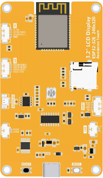
The ESP32-32E Display is a versatile microcontroller module that combines powerful processing capabilities with integrated Wi-Fi and Bluetooth connectivity. It is specifically designed for Internet of Things (IoT) applications, enabling seamless communication and control in connected environments. The module also features a display interface, allowing developers to create projects with graphical user interfaces for enhanced user interaction.
Explore Projects Built with ESP32-32E Display


Explore Projects Built with ESP32-32E Display
Common Applications and Use Cases
- Smart home automation systems
- IoT-enabled devices with visual feedback
- Wearable technology with graphical displays
- Data logging and monitoring with real-time visualization
- Educational projects and prototyping
Technical Specifications
Key Technical Details
| Parameter | Specification |
|---|---|
| Microcontroller | ESP32 dual-core processor |
| Clock Speed | Up to 240 MHz |
| Flash Memory | 4 MB (varies by model) |
| SRAM | 520 KB |
| Connectivity | Wi-Fi 802.11 b/g/n, Bluetooth 4.2 |
| Display Interface | SPI/I2C (compatible with OLED, TFT) |
| Operating Voltage | 3.3V |
| Input Voltage Range | 5V (via USB) or 3.3V (via pins) |
| GPIO Pins | 34 (multipurpose) |
| Power Consumption | Low-power modes available |
| Dimensions | 51mm x 25.5mm |
Pin Configuration and Descriptions
| Pin Name | Pin Number | Description |
|---|---|---|
| VIN | 1 | Input voltage (5V from USB or external) |
| GND | 2 | Ground |
| 3V3 | 3 | 3.3V output for peripherals |
| EN | 4 | Enable pin (active high) |
| GPIO0 | 5 | General-purpose I/O, boot mode select |
| GPIO1 | 6 | UART TX (default) |
| GPIO3 | 7 | UART RX (default) |
| GPIO12 | 8 | General-purpose I/O |
| GPIO13 | 9 | General-purpose I/O |
| GPIO14 | 10 | General-purpose I/O |
| GPIO15 | 11 | General-purpose I/O |
| GPIO16 | 12 | General-purpose I/O |
| GPIO17 | 13 | General-purpose I/O |
| SPI_CLK | 14 | SPI clock signal |
| SPI_MOSI | 15 | SPI data out |
| SPI_MISO | 16 | SPI data in |
| I2C_SCL | 17 | I2C clock signal |
| I2C_SDA | 18 | I2C data signal |
Usage Instructions
How to Use the ESP32-32E Display in a Circuit
- Powering the Module: Connect the VIN pin to a 5V power source (e.g., USB) or supply 3.3V directly to the 3V3 pin. Ensure the GND pin is connected to the ground of your circuit.
- Connecting the Display: Use the SPI or I2C pins to interface with your display module. Ensure the display's voltage requirements match the ESP32-32E's output.
- Programming the Module: Use the Arduino IDE or ESP-IDF to upload code. Select "ESP32 Dev Module" as the board in the IDE settings.
- Wi-Fi and Bluetooth Setup: Configure the Wi-Fi and Bluetooth settings in your code to enable connectivity.
Important Considerations and Best Practices
- Use level shifters if connecting 5V peripherals to the ESP32-32E, as its GPIO pins operate at 3.3V.
- Avoid drawing excessive current from the 3V3 pin to prevent instability.
- Ensure proper decoupling capacitors are used to stabilize the power supply.
- Use pull-up resistors for I2C communication if not already included in your display module.
Example Code for Display with Arduino UNO
Below is an example of using the ESP32-32E Display with an OLED screen via I2C:
#include <Wire.h>
#include <Adafruit_GFX.h>
#include <Adafruit_SSD1306.h>

// Define OLED display dimensions
#define SCREEN_WIDTH 128
#define SCREEN_HEIGHT 64

// Initialize the OLED display object
Adafruit_SSD1306 display(SCREEN_WIDTH, SCREEN_HEIGHT, &Wire, -1);

void setup() {
  // Start serial communication for debugging
  Serial.begin(115200);

  // Initialize the display
  if (!display.begin(SSD1306_I2C_ADDRESS, 0x3C)) {
    Serial.println(F("SSD1306 allocation failed"));
    while (true); // Halt execution if display initialization fails
  }

  // Clear the display buffer
  display.clearDisplay();

  // Display a welcome message
  display.setTextSize(1); // Set text size
  display.setTextColor(SSD1306_WHITE); // Set text color
  display.setCursor(0, 0); // Set cursor position
  display.println(F("ESP32-32E Display Test"));
  display.display(); // Render the text on the screen
  delay(2000); // Wait for 2 seconds
}

void loop() {
  // Clear the display buffer
  display.clearDisplay();

  // Display dynamic content
  display.setCursor(0, 0);
  display.println(F("Hello, IoT World!"));
  display.println(F("ESP32-32E is running."));
  display.display(); // Render the text on the screen

  delay(1000); // Update every second
}
Troubleshooting and FAQs
Common Issues and Solutions
Display Not Turning On:
- Ensure the display is properly connected to the I2C or SPI pins.
- Verify the display's power requirements and connections.
Wi-Fi Connection Fails:
- Double-check the SSID and password in your code.
- Ensure the ESP32-32E is within range of the Wi-Fi network.
Code Upload Fails:
- Ensure the correct board and port are selected in the Arduino IDE.
- Press and hold the BOOT button on the ESP32-32E while uploading.
Unstable Operation:
- Check for power supply issues or excessive current draw.
- Use proper decoupling capacitors near the power pins.
FAQs
Can I use the ESP32-32E Display with a 5V display module?
- Yes, but you will need level shifters to convert the 3.3V logic to 5V.
What is the maximum range of the Wi-Fi module?
- The range depends on environmental factors but typically extends up to 50 meters indoors.
Can I use the ESP32-32E Display for battery-powered projects?
- Yes, the module supports low-power modes for energy-efficient operation.
Is the ESP32-32E compatible with Arduino libraries?
- Yes, it is fully compatible with most Arduino libraries, including those for displays and sensors.