
Cirkit Designer
Your all-in-one circuit design IDE
Home /
Component Documentation
How to Use 4 Channel Relay Module: Examples, Pinouts, and Specs
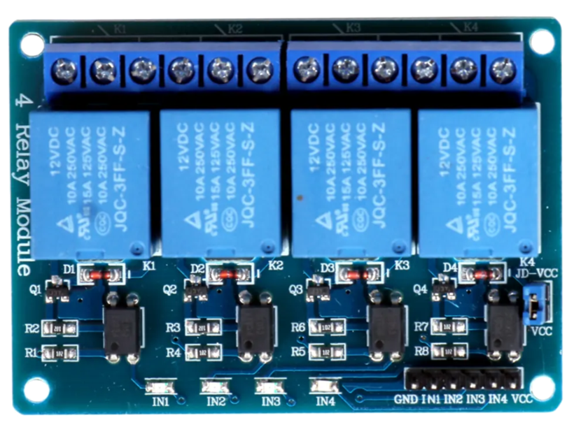
 Design with 4 Channel Relay Module in Cirkit Designer
Introduction
- The 4 Channel Relay Module is an electronic component designed to control multiple high-voltage devices using low-voltage signals. It features four independent relays, each capable of switching high-power loads while isolating the control circuit from the load circuit.
- Common applications include home automation, industrial control systems, robotics, and IoT projects. It is widely used to control lights, motors, fans, and other high-power devices safely and efficiently.
Explore Projects Built with 4 Channel Relay Module
Arduino-Controlled Relay Switch with Pushbutton Activation
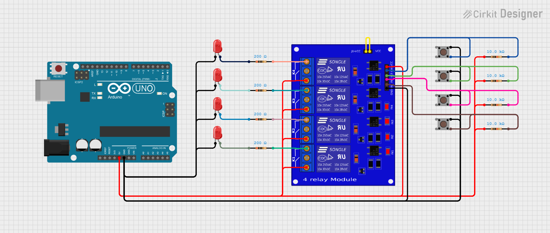
This circuit utilizes a 4-channel relay module controlled by an Arduino UNO, allowing for the switching of multiple devices based on input from several pushbuttons. Each pushbutton can activate a corresponding relay channel, which can be used to control various loads, while LEDs provide visual feedback for the relay states.
Open Project in Cirkit DesignerBattery-Powered 4-Channel Relay Control with LED Indicators
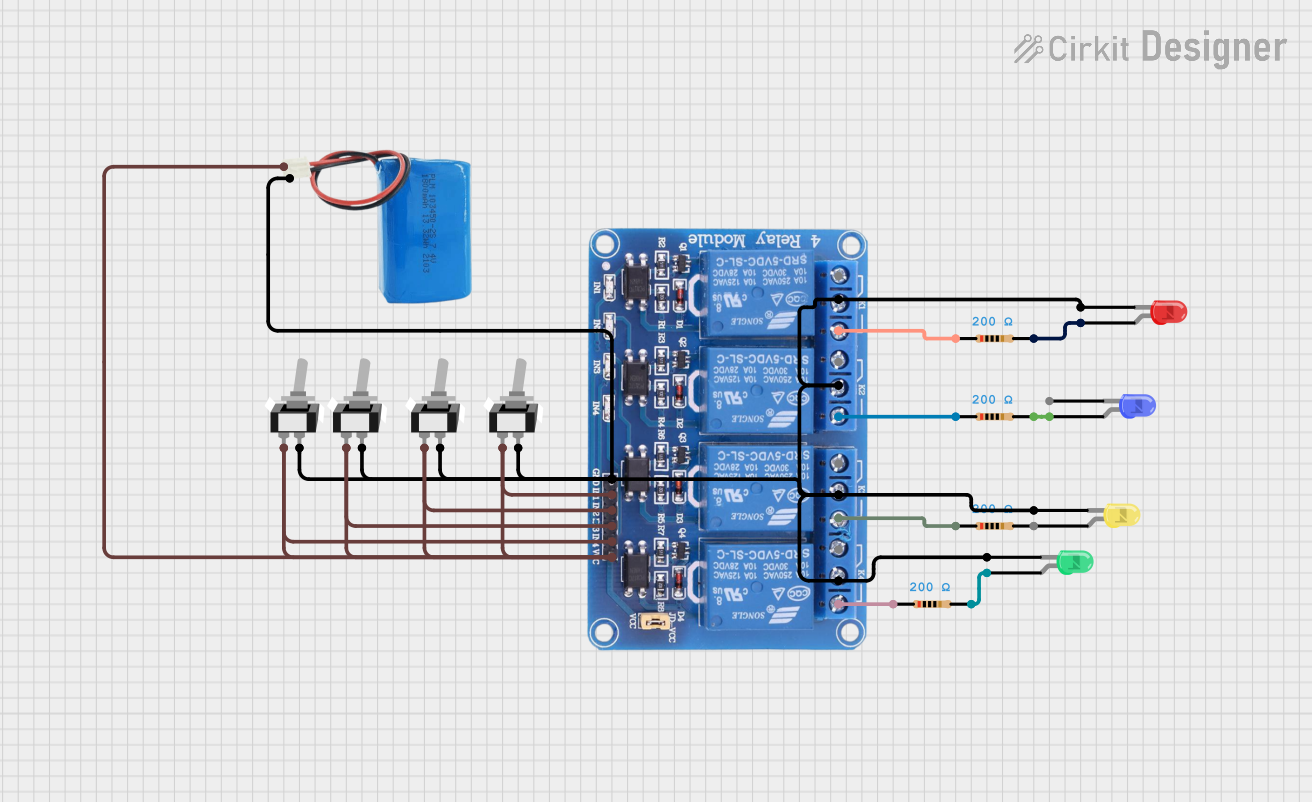
This circuit consists of a 5V battery powering a 4-channel relay module, which controls four LEDs (red, yellow, green, and blue) through individual resistors. Each relay channel is activated by a corresponding SPST toggle switch, allowing manual control of the LEDs.
Open Project in Cirkit DesignerDC-DC Converter and Relay Module Power Distribution System
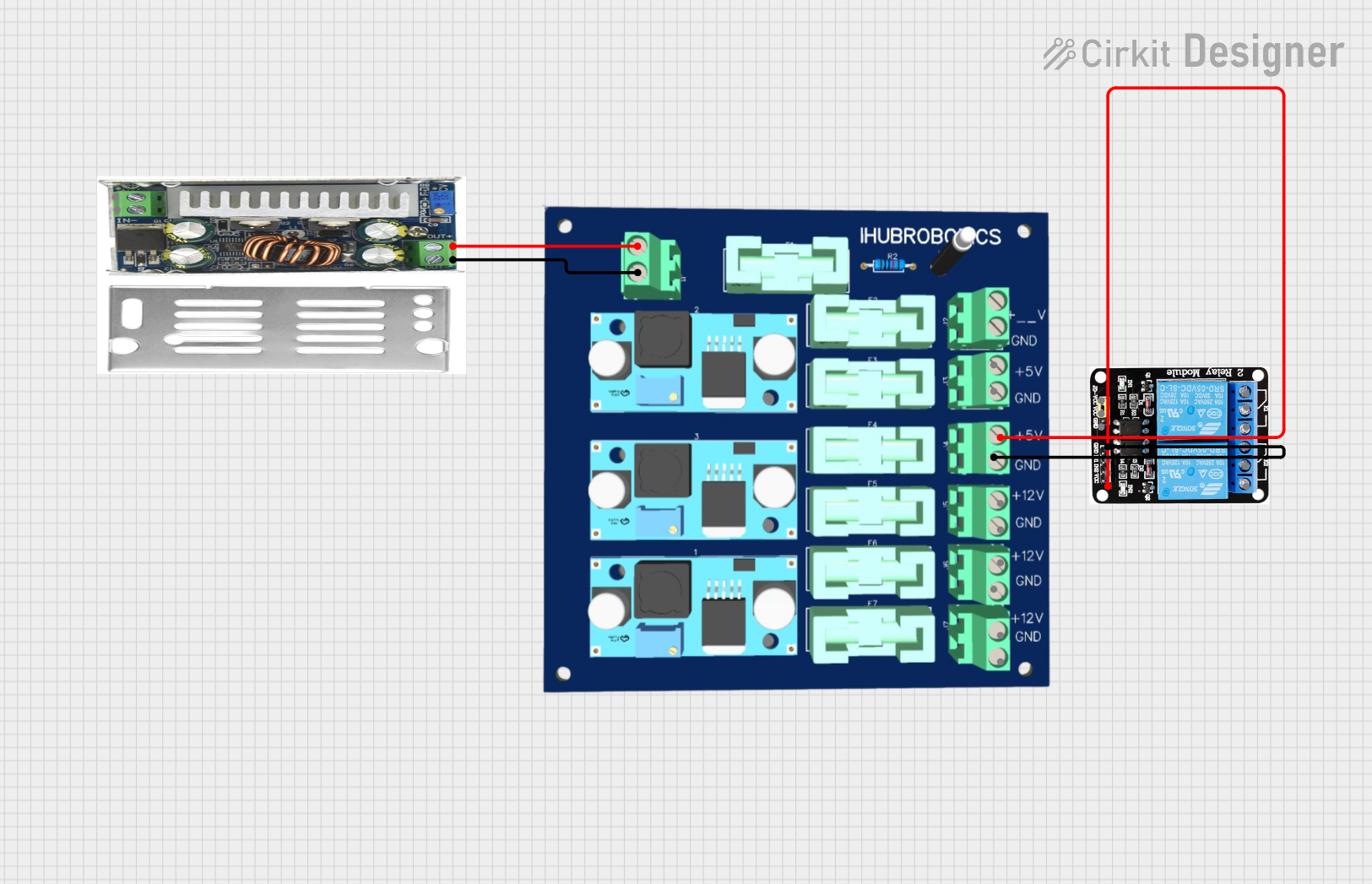
This circuit consists of a DC-DC converter powering a 6-channel power module, which in turn supplies 5V to a 2-relay module. The power module distributes the converted voltage to the relay module, enabling it to control external devices.
Open Project in Cirkit DesignerArduino UNO Controlled Smart Lighting System with Relay and Micro Switches
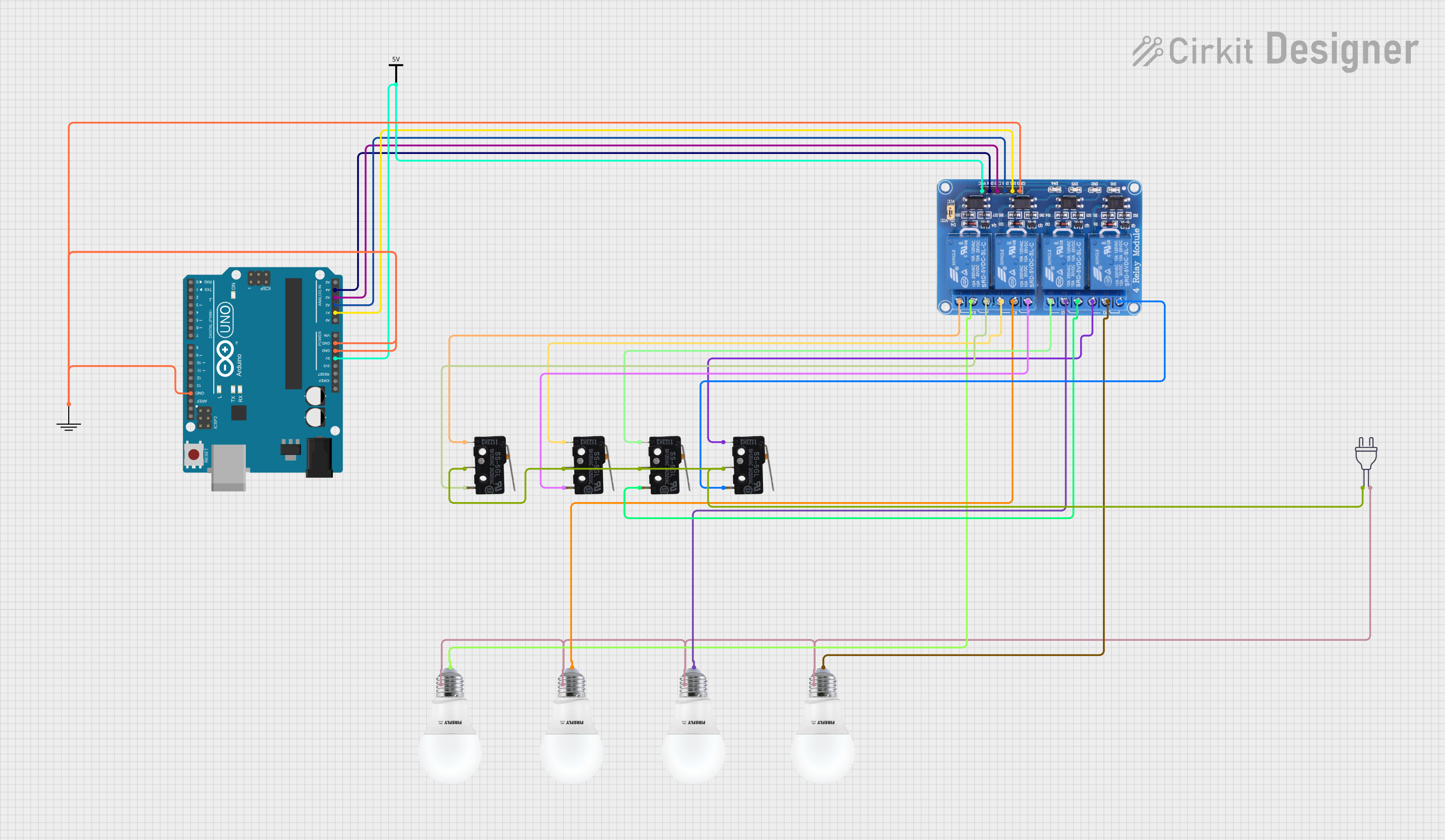
This circuit uses an Arduino UNO to control a 4-channel relay module, which in turn controls four bulbs. Each relay channel is connected to a bulb and can be toggled by corresponding micro switches, allowing for manual control of the bulbs.
Open Project in Cirkit DesignerExplore Projects Built with 4 Channel Relay Module
Arduino-Controlled Relay Switch with Pushbutton Activation
This circuit utilizes a 4-channel relay module controlled by an Arduino UNO, allowing for the switching of multiple devices based on input from several pushbuttons. Each pushbutton can activate a corresponding relay channel, which can be used to control various loads, while LEDs provide visual feedback for the relay states.
Open Project in Cirkit DesignerBattery-Powered 4-Channel Relay Control with LED Indicators
This circuit consists of a 5V battery powering a 4-channel relay module, which controls four LEDs (red, yellow, green, and blue) through individual resistors. Each relay channel is activated by a corresponding SPST toggle switch, allowing manual control of the LEDs.
Open Project in Cirkit DesignerDC-DC Converter and Relay Module Power Distribution System
This circuit consists of a DC-DC converter powering a 6-channel power module, which in turn supplies 5V to a 2-relay module. The power module distributes the converted voltage to the relay module, enabling it to control external devices.
Open Project in Cirkit DesignerArduino UNO Controlled Smart Lighting System with Relay and Micro Switches
This circuit uses an Arduino UNO to control a 4-channel relay module, which in turn controls four bulbs. Each relay channel is connected to a bulb and can be toggled by corresponding micro switches, allowing for manual control of the bulbs.
Open Project in Cirkit DesignerTechnical Specifications
- Operating Voltage: 5V DC
- Trigger Voltage: 3.3V to 5V (compatible with most microcontrollers, including Arduino)
- Relay Type: SPDT (Single Pole Double Throw)
- Maximum Load:
- AC: 250V at 10A
- DC: 30V at 10A
- Isolation: Optocoupler-based isolation between control and load circuits
- Indicator LEDs: One LED per relay to indicate activation status
- Dimensions: Approximately 75mm x 55mm x 20mm
Pin Configuration and Descriptions
Input Pins (Control Side)
| Pin Name | Description |
|---|---|
| VCC | Connect to 5V DC power supply to power the module. |
| GND | Connect to ground of the power supply or microcontroller. |
| IN1 | Control signal for Relay 1 (Active LOW). |
| IN2 | Control signal for Relay 2 (Active LOW). |
| IN3 | Control signal for Relay 3 (Active LOW). |
| IN4 | Control signal for Relay 4 (Active LOW). |
Output Pins (Load Side)
| Relay Terminal | Description |
|---|---|
| COM (x4) | Common terminal for each relay. Connect to the power source or load. |
| NO (x4) | Normally Open terminal. Connect to the load for default OFF state. |
| NC (x4) | Normally Closed terminal. Connect to the load for default ON state. |
Usage Instructions
How to Use the 4 Channel Relay Module in a Circuit
- Power the Module: Connect the VCC pin to a 5V DC power supply and the GND pin to ground.
- Connect the Control Signals: Use digital output pins from a microcontroller (e.g., Arduino) to connect to the IN1, IN2, IN3, and IN4 pins. A LOW signal activates the corresponding relay.
- Connect the Load:
- For each relay, connect the load to the COM and NO terminals if you want the load to be OFF by default.
- Alternatively, connect the load to the COM and NC terminals if you want the load to be ON by default.
- Test the Circuit: Upload the control code to the microcontroller and verify the relays switch as expected.
Important Considerations and Best Practices
- Ensure the relay module is powered with a stable 5V DC supply.
- Do not exceed the maximum load ratings of the relays (250V AC/10A or 30V DC/10A).
- Use proper insulation and safety precautions when working with high-voltage loads.
- Avoid switching inductive loads (e.g., motors) without using a flyback diode or snubber circuit to prevent voltage spikes.
- If using with an Arduino UNO, ensure the ground of the relay module is connected to the Arduino's ground.
Example Code for Arduino UNO
// Example code to control a 4 Channel Relay Module with an Arduino UNO
// Each relay is controlled by a digital pin on the Arduino

// Define the pins connected to the relay module
#define RELAY1 2  // Pin connected to IN1
#define RELAY2 3  // Pin connected to IN2
#define RELAY3 4  // Pin connected to IN3
#define RELAY4 5  // Pin connected to IN4

void setup() {
  // Set relay pins as outputs
  pinMode(RELAY1, OUTPUT);
  pinMode(RELAY2, OUTPUT);
  pinMode(RELAY3, OUTPUT);
  pinMode(RELAY4, OUTPUT);

  // Initialize all relays to OFF (HIGH state)
  digitalWrite(RELAY1, HIGH);
  digitalWrite(RELAY2, HIGH);
  digitalWrite(RELAY3, HIGH);
  digitalWrite(RELAY4, HIGH);
}

void loop() {
  // Example sequence to toggle relays ON and OFF
  digitalWrite(RELAY1, LOW); // Turn ON Relay 1
  delay(1000);              // Wait for 1 second
  digitalWrite(RELAY1, HIGH); // Turn OFF Relay 1
  delay(1000);              // Wait for 1 second

  digitalWrite(RELAY2, LOW); // Turn ON Relay 2
  delay(1000);              // Wait for 1 second
  digitalWrite(RELAY2, HIGH); // Turn OFF Relay 2
  delay(1000);              // Wait for 1 second

  digitalWrite(RELAY3, LOW); // Turn ON Relay 3
  delay(1000);              // Wait for 1 second
  digitalWrite(RELAY3, HIGH); // Turn OFF Relay 3
  delay(1000);              // Wait for 1 second

  digitalWrite(RELAY4, LOW); // Turn ON Relay 4
  delay(1000);              // Wait for 1 second
  digitalWrite(RELAY4, HIGH); // Turn OFF Relay 4
  delay(1000);              // Wait for 1 second
}
Troubleshooting and FAQs
Common Issues
Relays Not Activating:
- Ensure the module is powered with a stable 5V DC supply.
- Verify the control signals from the microcontroller are set to LOW to activate the relays.
- Check the wiring between the microcontroller and the relay module.
Load Not Switching:
- Confirm the load is connected to the correct relay terminals (COM and NO/NC).
- Ensure the load does not exceed the relay's maximum current and voltage ratings.
Indicator LEDs Not Lighting Up:
- Check the power supply to the relay module.
- Verify the control signal connections and ensure the microcontroller is functioning correctly.
FAQs
Can I use the relay module with a 3.3V microcontroller?
Yes, the module is compatible with 3.3V control signals, but ensure the VCC pin is still powered with 5V.What happens if I exceed the relay's load ratings?
Exceeding the load ratings can damage the relay contacts and may pose a safety hazard. Always stay within the specified limits.Can I control AC and DC loads simultaneously?
Yes, as long as each relay's load does not exceed its maximum ratings and proper isolation is maintained.Why do I hear a clicking sound from the relays?
The clicking sound is normal and indicates the mechanical switching of the relay contacts.