Cirkit Designer
Your all-in-one circuit design IDE
Home /
Component Documentation
How to Use IR LED: Examples, Pinouts, and Specs
Introduction
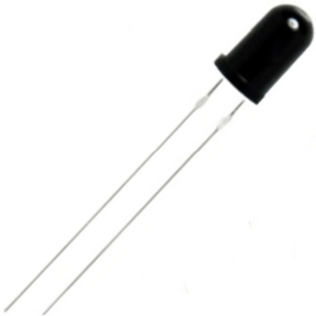
The IR LED (Infrared Light Emitting Diode) manufactured by ARDUINO with part ID LED is a versatile component that emits light in the infrared spectrum, which is invisible to the human eye. This component is widely used in applications such as remote controls, night-vision devices, and various sensing applications. Its ability to emit infrared light makes it an essential component in many electronic projects and devices.
Explore Projects Built with IR LED
IR Sensor-Controlled Relay with LED Indicator
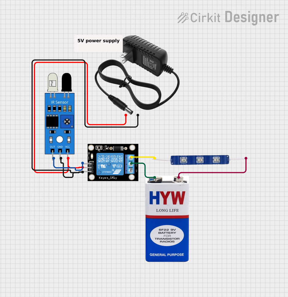
This circuit uses an IR sensor to control a relay module, which in turn switches a 12V blue LED on and off. The IR sensor output is connected to the signal input of the relay, enabling the sensor to activate the relay. The relay's normally closed (NC) contact is connected to the LED, allowing the LED to be powered by a 9V battery when the relay is not activated by the IR sensor.
Arduino Leonardo-Based IR Sensor-Controlled LED System
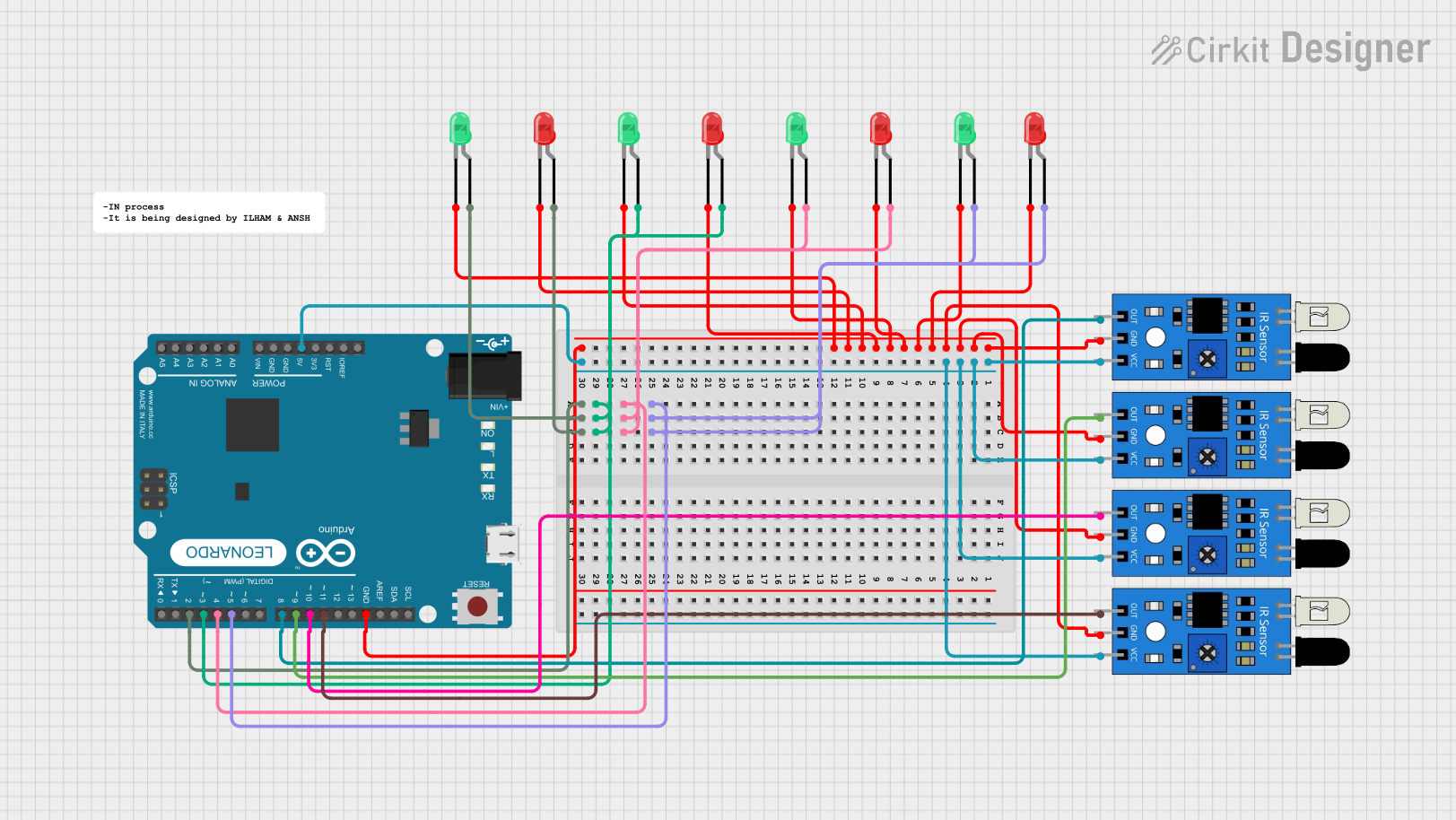
This circuit uses an Arduino Leonardo to control multiple LEDs based on input from four IR sensors. Each IR sensor is connected to a digital pin on the Arduino, and each LED pair (one red and one green) is connected to another digital pin. When an IR sensor detects an object, the corresponding pair of LEDs will light up.
Arduino UNO Based IR Sensor Controlled LED
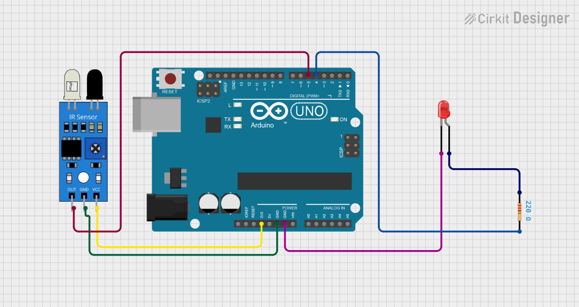
This circuit is designed to detect an object using an IR sensor and signal the detection through a red LED. The IR sensor is powered by the Arduino UNO's 3.3V output and its output is connected to digital pin D5 on the Arduino. The LED is connected to digital pin D4 through a 220 Ohm resistor to limit current, and its cathode is grounded to the Arduino.
Arduino UNO Controlled IR Sensor with LED Indicator
This circuit consists of an Arduino UNO connected to an IR sensor and a red LED. The IR sensor is powered by the Arduino's 5V output and its signal output is connected to the Arduino's digital pin D2. The red LED's anode is connected to the Arduino's digital pin D13, and its cathode is grounded, allowing the Arduino to control the LED based on the IR sensor's output.
Explore Projects Built with IR LED
IR Sensor-Controlled Relay with LED Indicator
This circuit uses an IR sensor to control a relay module, which in turn switches a 12V blue LED on and off. The IR sensor output is connected to the signal input of the relay, enabling the sensor to activate the relay. The relay's normally closed (NC) contact is connected to the LED, allowing the LED to be powered by a 9V battery when the relay is not activated by the IR sensor.
Arduino Leonardo-Based IR Sensor-Controlled LED System
This circuit uses an Arduino Leonardo to control multiple LEDs based on input from four IR sensors. Each IR sensor is connected to a digital pin on the Arduino, and each LED pair (one red and one green) is connected to another digital pin. When an IR sensor detects an object, the corresponding pair of LEDs will light up.
Arduino UNO Based IR Sensor Controlled LED
This circuit is designed to detect an object using an IR sensor and signal the detection through a red LED. The IR sensor is powered by the Arduino UNO's 3.3V output and its output is connected to digital pin D5 on the Arduino. The LED is connected to digital pin D4 through a 220 Ohm resistor to limit current, and its cathode is grounded to the Arduino.
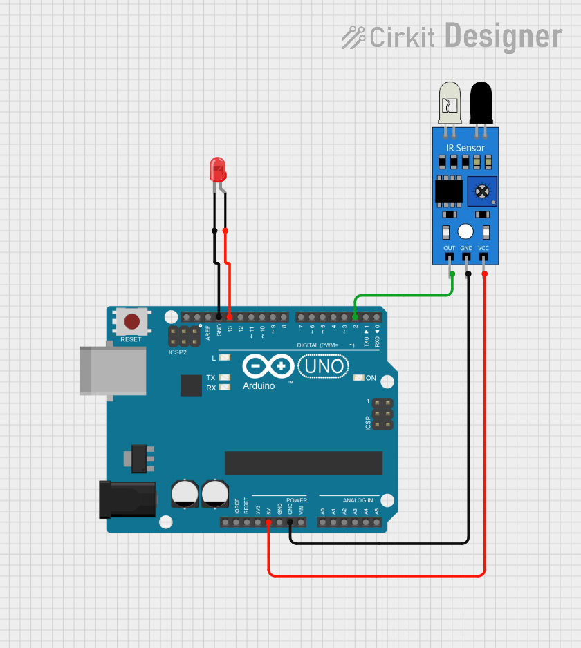
Arduino UNO Controlled IR Sensor with LED Indicator
This circuit consists of an Arduino UNO connected to an IR sensor and a red LED. The IR sensor is powered by the Arduino's 5V output and its signal output is connected to the Arduino's digital pin D2. The red LED's anode is connected to the Arduino's digital pin D13, and its cathode is grounded, allowing the Arduino to control the LED based on the IR sensor's output.
Technical Specifications
Key Technical Details
| Parameter | Value |
|---|---|
| Forward Voltage | 1.2V - 1.4V |
| Forward Current | 20mA |
| Power Rating | 30mW |
| Wavelength | 850nm - 940nm |
| Viewing Angle | 20° - 30° |
| Package Type | Through-hole |
Pin Configuration and Descriptions
| Pin Number | Pin Name | Description |
|---|---|---|
| 1 | Anode | Positive terminal (longer lead) |
| 2 | Cathode | Negative terminal (shorter lead) |
Usage Instructions
How to Use the Component in a Circuit
- Identify the Pins: The IR LED has two pins: the longer lead is the anode (positive), and the shorter lead is the cathode (negative).
- Connect to Power Source: Connect the anode to the positive terminal of the power source (e.g., 5V from an Arduino UNO) through a current-limiting resistor (typically 220Ω to 330Ω). Connect the cathode to the ground (GND).
- Current Limiting Resistor: Use a resistor to limit the current flowing through the IR LED to prevent damage. The value of the resistor can be calculated using Ohm's Law: ( R = \frac{V_{supply} - V_{forward}}{I_{forward}} ).
Example Circuit with Arduino UNO
- Connect the anode of the IR LED to digital pin 3 of the Arduino UNO through a 220Ω resistor.
- Connect the cathode of the IR LED to the GND pin of the Arduino UNO.
Arduino Code Example
// Define the pin for the IR LED
const int irLedPin = 3;

void setup() {
  // Initialize the IR LED pin as an output
  pinMode(irLedPin, OUTPUT);
}

void loop() {
  // Turn the IR LED on
  digitalWrite(irLedPin, HIGH);
  delay(1000); // Keep the LED on for 1 second

  // Turn the IR LED off
  digitalWrite(irLedPin, LOW);
  delay(1000); // Keep the LED off for 1 second
}
Important Considerations and Best Practices
- Current Limiting: Always use a current-limiting resistor to prevent excessive current from damaging the IR LED.
- Polarity: Ensure correct polarity when connecting the IR LED. Reversing the connections can damage the component.
- Heat Dissipation: Although IR LEDs typically operate at low power, ensure adequate ventilation to prevent overheating in high-power applications.
Troubleshooting and FAQs
Common Issues Users Might Face
- IR LED Not Emitting Light:
- Solution: Verify the connections and ensure the correct polarity. Check the resistor value to ensure it is appropriate for the circuit.
- IR LED Overheating:
- Solution: Ensure the current-limiting resistor is of the correct value. Check for any short circuits in the wiring.
- Inconsistent Performance:
- Solution: Verify the power supply voltage and ensure stable connections. Check for any loose or corroded connections.
FAQs
Can I see the light emitted by the IR LED?
- No, the light emitted by the IR LED is in the infrared spectrum and is invisible to the human eye. You can use a camera or a smartphone to see the IR light.
What is the typical range of an IR LED?
- The range depends on the power of the IR LED and the sensitivity of the receiver. Typically, it can range from a few centimeters to several meters.
Can I use an IR LED with any microcontroller?
- Yes, you can use an IR LED with any microcontroller as long as you provide the correct voltage and current through a current-limiting resistor.
By following this documentation, users can effectively integrate the ARDUINO IR LED into their projects, ensuring proper usage and troubleshooting any issues that may arise.