Cirkit Designer Logo
Cirkit Designer
Your all-in-one circuit design IDE
Home / 
Component Documentation

How to Use terminalblock-04-01: Examples, Pinouts, and Specs

Image of terminalblock-04-01
Cirkit Designer LogoDesign with terminalblock-04-01 in Cirkit Designer

Introduction

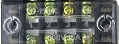
The TerminalBlock-04-01 is a versatile and reliable terminal block designed for connecting multiple wires together in a secure and organized manner. It features four connection points and utilizes screw terminals for easy wire insertion and removal. This component is widely used in electrical and electronic systems to simplify wiring, ensure robust connections, and facilitate maintenance.

Explore Projects Built with terminalblock-04-01

Use Cirkit Designer to design, explore, and prototype these projects online. Some projects support real-time simulation. Click "Open Project" to start designing instantly!
Modular Power Distribution System with Multiple SMPS Units and 120V Outlet
Image of Cellion-Tesla: A project utilizing terminalblock-04-01 in a practical application
This circuit is designed to convert 240V AC power to both 12V and 24V DC outputs using multiple SMPS units. Terminal blocks are used to organize and distribute the power, while a 120V outlet provides additional AC power access. The circuit is likely used for powering various electronic devices that require different voltage levels.
Cirkit Designer LogoOpen Project in Cirkit Designer
Peltier-Controlled Thermal Management System with SPST Switch
Image of Mini car refrigerator circuit: A project utilizing terminalblock-04-01 in a practical application
This circuit consists of multiple Peltier modules and fans connected in parallel to a digital power supply, with a rocker switch (SPST) controlling the power flow to one of the Peltier modules and multiple fans. The 2.1mm Barrel Jack with Terminal Block serves as the power input connector, and the rocker switch allows for selective enabling or disabling of the connected devices. The circuit is designed to provide cooling or heating through the Peltier modules while the fans assist in heat dissipation or air circulation.
Cirkit Designer LogoOpen Project in Cirkit Designer
Battery-Powered Relay Control System with Directional Switch
Image of Skema Lampu D2: A project utilizing terminalblock-04-01 in a practical application
This circuit involves a 12V battery powering a relay system controlled by a directional switch. The relays are connected through terminal blocks and are used to switch between different outputs, indicated by the AdaGator Top components.
Cirkit Designer LogoOpen Project in Cirkit Designer
Mega2560-Controlled Automation System with Non-Contact Liquid Level Sensing and Motor Control
Image of Project_AutomaticBartender: A project utilizing terminalblock-04-01 in a practical application
This circuit appears to be a complex control system centered around an Arduino Mega2560 R3 Pro microcontroller, which interfaces with multiple sensors (XKC-Y26-V non-contact liquid level sensors and an LM35 temperature sensor), servo motors, a touch display, and an IBT-2 H-Bridge motor driver for controlling a planetary gearbox motor. The system also includes a UART TTL to RS485 converter for communication, likely with the touch display, and a power management subsystem with a switching power supply, fuses, and circuit breakers for safety and voltage regulation (XL4016). The absence of embedded code suggests that the functionality of the microcontroller is not defined within the provided data.
Cirkit Designer LogoOpen Project in Cirkit Designer

Explore Projects Built with terminalblock-04-01

Use Cirkit Designer to design, explore, and prototype these projects online. Some projects support real-time simulation. Click "Open Project" to start designing instantly!
Image of Cellion-Tesla: A project utilizing terminalblock-04-01 in a practical application
Modular Power Distribution System with Multiple SMPS Units and 120V Outlet
This circuit is designed to convert 240V AC power to both 12V and 24V DC outputs using multiple SMPS units. Terminal blocks are used to organize and distribute the power, while a 120V outlet provides additional AC power access. The circuit is likely used for powering various electronic devices that require different voltage levels.
Cirkit Designer LogoOpen Project in Cirkit Designer
Image of Mini car refrigerator circuit: A project utilizing terminalblock-04-01 in a practical application
Peltier-Controlled Thermal Management System with SPST Switch
This circuit consists of multiple Peltier modules and fans connected in parallel to a digital power supply, with a rocker switch (SPST) controlling the power flow to one of the Peltier modules and multiple fans. The 2.1mm Barrel Jack with Terminal Block serves as the power input connector, and the rocker switch allows for selective enabling or disabling of the connected devices. The circuit is designed to provide cooling or heating through the Peltier modules while the fans assist in heat dissipation or air circulation.
Cirkit Designer LogoOpen Project in Cirkit Designer
Image of Skema Lampu D2: A project utilizing terminalblock-04-01 in a practical application
Battery-Powered Relay Control System with Directional Switch
This circuit involves a 12V battery powering a relay system controlled by a directional switch. The relays are connected through terminal blocks and are used to switch between different outputs, indicated by the AdaGator Top components.
Cirkit Designer LogoOpen Project in Cirkit Designer
Image of Project_AutomaticBartender: A project utilizing terminalblock-04-01 in a practical application
Mega2560-Controlled Automation System with Non-Contact Liquid Level Sensing and Motor Control
This circuit appears to be a complex control system centered around an Arduino Mega2560 R3 Pro microcontroller, which interfaces with multiple sensors (XKC-Y26-V non-contact liquid level sensors and an LM35 temperature sensor), servo motors, a touch display, and an IBT-2 H-Bridge motor driver for controlling a planetary gearbox motor. The system also includes a UART TTL to RS485 converter for communication, likely with the touch display, and a power management subsystem with a switching power supply, fuses, and circuit breakers for safety and voltage regulation (XL4016). The absence of embedded code suggests that the functionality of the microcontroller is not defined within the provided data.
Cirkit Designer LogoOpen Project in Cirkit Designer

Common Applications and Use Cases

  • Industrial control panels and automation systems
  • Power distribution in electrical circuits
  • Prototyping and testing of electronic circuits
  • Home and building electrical installations
  • Securely connecting wires in DIY electronics projects

Technical Specifications

The TerminalBlock-04-01 is designed to handle a wide range of electrical and mechanical requirements. Below are its key technical specifications:

Parameter Value
Number of Terminals 4
Terminal Type Screw clamp
Wire Size Compatibility 22 AWG to 12 AWG
Maximum Voltage Rating 300V AC/DC
Maximum Current Rating 15A
Material Flame-retardant thermoplastic
Mounting Type PCB mount or DIN rail compatible
Operating Temperature -40°C to +105°C

Pin Configuration and Descriptions

The TerminalBlock-04-01 has four screw terminals, each corresponding to a single connection point. Below is the pin configuration:

Pin Number Description
1 Terminal for wire connection 1
2 Terminal for wire connection 2
3 Terminal for wire connection 3
4 Terminal for wire connection 4

Each terminal is independent, allowing for flexible wiring configurations.

Usage Instructions

How to Use the TerminalBlock-04-01 in a Circuit

  1. Prepare the Wires: Strip the insulation from the ends of the wires you wish to connect. Ensure the exposed conductor length matches the terminal block's specifications (typically 5-7mm).
  2. Insert the Wires: Loosen the screw on the terminal using a screwdriver. Insert the stripped wire into the terminal opening.
  3. Secure the Connection: Tighten the screw to clamp the wire securely. Avoid overtightening, as this may damage the wire or terminal.
  4. Verify the Connection: Gently tug on the wire to ensure it is firmly secured in the terminal.

Important Considerations and Best Practices

  • Wire Compatibility: Ensure the wire gauge is within the supported range (22 AWG to 12 AWG).
  • Avoid Overloading: Do not exceed the maximum voltage (300V) or current (15A) ratings.
  • Proper Mounting: If using the PCB mount version, solder the pins securely to the PCB. For DIN rail mounting, ensure the block is properly clipped onto the rail.
  • Insulation: Use insulated wires to prevent accidental short circuits.
  • Maintenance: Periodically check the screws for tightness, especially in environments with vibration.

Example: Connecting to an Arduino UNO

The TerminalBlock-04-01 can be used to connect external components, such as sensors or motors, to an Arduino UNO. Below is an example of wiring a 12V DC motor through the terminal block:

  1. Connect the motor's positive and negative wires to terminals 1 and 2 of the TerminalBlock-04-01.
  2. Use terminals 3 and 4 to connect the power supply to the motor.
  3. Optionally, add a diode across the motor terminals to protect against back EMF.

Here is a simple Arduino code snippet to control the motor using a relay:

// Define the relay pin connected to the Arduino
const int relayPin = 7;

void setup() {
  pinMode(relayPin, OUTPUT); // Set the relay pin as an output
  digitalWrite(relayPin, LOW); // Ensure the relay is off initially
}

void loop() {
  digitalWrite(relayPin, HIGH); // Turn the motor on
  delay(5000); // Run the motor for 5 seconds
  digitalWrite(relayPin, LOW); // Turn the motor off
  delay(5000); // Wait for 5 seconds before restarting
}

Note: Ensure the relay module is properly connected to the Arduino and the terminal block is used to organize the motor and power supply connections.

Troubleshooting and FAQs

Common Issues and Solutions

  1. Loose Connections

    • Issue: Wires are not securely held in the terminal.
    • Solution: Ensure the screws are tightened properly. Check that the wire is stripped to the correct length.
  2. Overheating

    • Issue: The terminal block becomes hot during operation.
    • Solution: Verify that the current does not exceed the 15A rating. Use thicker wires if necessary.
  3. Wire Slippage

    • Issue: Wires slip out of the terminal under vibration.
    • Solution: Re-tighten the screws and consider using ferrules for better grip.
  4. Corrosion

    • Issue: Terminals show signs of corrosion over time.
    • Solution: Use the terminal block in a dry environment or select a version with corrosion-resistant plating.

FAQs

Q1: Can I use the TerminalBlock-04-01 for high-frequency signals?
A1: While the terminal block can handle low-frequency signals, it is not ideal for high-frequency applications due to potential signal degradation.

Q2: Is the TerminalBlock-04-01 suitable for outdoor use?
A2: The standard version is not weatherproof. For outdoor use, consider an enclosure or a weather-resistant terminal block.

Q3: Can I connect wires of different gauges to the same terminal block?
A3: Yes, as long as the wire gauges are within the supported range (22 AWG to 12 AWG).

Q4: How do I mount the TerminalBlock-04-01 on a PCB?
A4: Align the pins with the PCB holes, solder them securely, and ensure proper alignment to avoid stress on the connections.

By following this documentation, you can effectively use the TerminalBlock-04-01 in your projects and ensure reliable and organized wiring.