How to Use microcontroller: Examples, Pinouts, and Specs
Introduction
The PIC12F1572-I/P is an 8-bit microcontroller manufactured by Microchip Technology Inc.. It is a compact and versatile integrated circuit designed for use in embedded systems. This microcontroller combines a processor core, memory, and programmable input/output (I/O) peripherals, making it ideal for controlling specific operations in a wide range of applications.
Explore Projects Built with microcontroller


Explore Projects Built with microcontroller
Common Applications and Use Cases
- Home automation systems
- Motor control and industrial automation
- Consumer electronics
- IoT (Internet of Things) devices
- LED lighting control
- Battery-powered devices
Technical Specifications
The PIC12F1572-I/P microcontroller is part of the PIC12 family and offers a balance of performance, low power consumption, and flexibility. Below are its key technical specifications:
General Specifications
| Parameter | Value |
|---|---|
| Architecture | 8-bit |
| Operating Voltage Range | 2.3V to 5.5V |
| CPU Speed | Up to 8 MHz (internal clock) |
| Flash Program Memory | 3.5 KB |
| SRAM | 256 bytes |
| EEPROM | 128 bytes |
| I/O Pins | 6 |
| Package Type | PDIP-8 |
| Temperature Range | -40°C to +85°C (Industrial) |
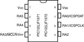
Pin Configuration and Descriptions
The PIC12F1572-I/P comes in an 8-pin PDIP package. Below is the pinout and description:
| Pin Number | Pin Name | Type | Description |
|---|---|---|---|
| 1 | VDD | Power | Positive supply voltage (2.3V to 5.5V) |
| 2 | GP5 | I/O | General-purpose I/O or PWM output |
| 3 | GP4 | I/O | General-purpose I/O or PWM output |
| 4 | GP3 | Input | General-purpose input or MCLR (reset) |
| 5 | GP2 | I/O | General-purpose I/O or PWM output |
| 6 | GP1 | I/O | General-purpose I/O or PWM output |
| 7 | GP0 | I/O | General-purpose I/O or PWM output |
| 8 | VSS | Power | Ground (0V reference) |
Usage Instructions
The PIC12F1572-I/P microcontroller is easy to integrate into embedded systems. Below are the steps and considerations for using it effectively:
How to Use the Component in a Circuit
- Power Supply: Connect the VDD pin to a stable power source (2.3V to 5.5V) and the VSS pin to ground.
- Reset Pin (MCLR): If using the MCLR function, connect a pull-up resistor (typically 10kΩ) to the GP3 pin. If not, configure GP3 as a general-purpose input.
- Clock Source: The microcontroller has an internal oscillator that can run up to 8 MHz. Configure the clock settings in the firmware.
- I/O Pins: Use the GP0 to GP5 pins for digital input/output or PWM signals. Configure these pins in the firmware as needed.
- Programming: Use a compatible programmer (e.g., PICkit 4) to load your firmware onto the microcontroller via the ICSP (In-Circuit Serial Programming) interface.
Important Considerations and Best Practices
- Decoupling Capacitor: Place a 0.1 µF ceramic capacitor close to the VDD and VSS pins to filter noise and stabilize the power supply.
- Unused Pins: Configure unused I/O pins as outputs or connect them to ground through a resistor to avoid floating states.
- Low Power Modes: Utilize the microcontroller's sleep mode to reduce power consumption in battery-powered applications.
- PWM Configuration: The PIC12F1572 features three PWM modules. Configure them in the firmware for applications like motor control or LED dimming.
Example Code for Arduino UNO Integration
Although the PIC12F1572 is not directly programmable via Arduino IDE, it can communicate with an Arduino UNO via I2C or UART. Below is an example of how to send data from an Arduino UNO to the PIC12F1572 using UART:
// Arduino UNO UART Example: Sending data to PIC12F1572
// Ensure the PIC12F1572 is configured to receive UART data.

void setup() {
  Serial.begin(9600); // Initialize UART at 9600 baud rate
}

void loop() {
  Serial.println("Hello, PIC12F1572!"); // Send data to the PIC
  delay(1000); // Wait for 1 second
}
Troubleshooting and FAQs
Common Issues and Solutions
Microcontroller Not Responding
- Cause: Incorrect power supply or missing decoupling capacitor.
- Solution: Verify the VDD and VSS connections and add a 0.1 µF capacitor.
Programming Failure
- Cause: Incorrect ICSP connections or unsupported programmer.
- Solution: Check the ICSP pin connections and ensure the programmer supports the PIC12F1572.
Unexpected Behavior
- Cause: Floating I/O pins or incorrect firmware configuration.
- Solution: Configure all unused pins as outputs or connect them to ground through resistors. Double-check the firmware settings.
PWM Output Not Working
- Cause: Incorrect PWM module configuration.
- Solution: Verify the PWM settings in the firmware and ensure the correct pins are used.
FAQs
Q1: Can I use an external oscillator with the PIC12F1572?
A1: Yes, the PIC12F1572 supports external oscillators. Connect the oscillator to the appropriate pins and configure the clock source in the firmware.
Q2: How do I protect the microcontroller from voltage spikes?
A2: Use a TVS diode or a zener diode across the power supply lines and add a decoupling capacitor near the VDD pin.
Q3: Can I use the PIC12F1572 for analog-to-digital conversion (ADC)?
A3: No, the PIC12F1572 does not have an ADC module. For ADC functionality, consider other PIC microcontrollers with built-in ADCs.
Q4: What is the maximum current the I/O pins can source or sink?
A4: Each I/O pin can source or sink up to 25 mA, with a total maximum current of 125 mA for all pins combined.
This concludes the documentation for the PIC12F1572-I/P microcontroller. For further details, refer to the official datasheet provided by Microchip Technology Inc..