How to Use Adafruit 24-Channel 12-bit PWM LED Driver - SPI: Examples, Pinouts, and Specs
Introduction
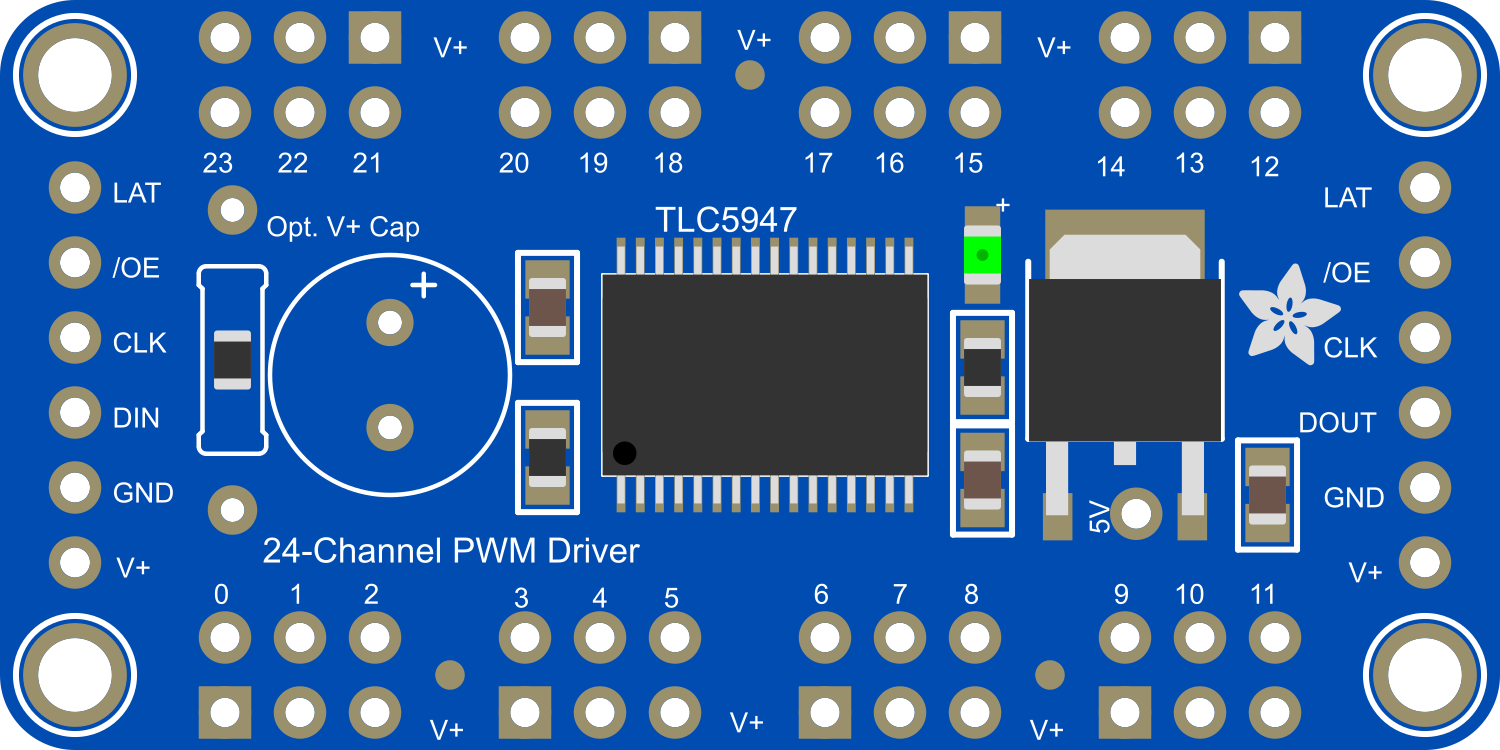
The Adafruit 24-Channel 12-bit PWM LED Driver is an efficient and versatile solution for controlling multiple LEDs. Utilizing Pulse Width Modulation (PWM), this driver can manage the brightness of up to 24 individual LEDs with 12-bit resolution, allowing for smooth and precise light output control. The module communicates via the Serial Peripheral Interface (SPI), making it compatible with a wide range of microcontrollers, including Arduino boards. Common applications include LED displays, lighting projects, and custom electronics requiring variable LED intensity.
Explore Projects Built with Adafruit 24-Channel 12-bit PWM LED Driver - SPI
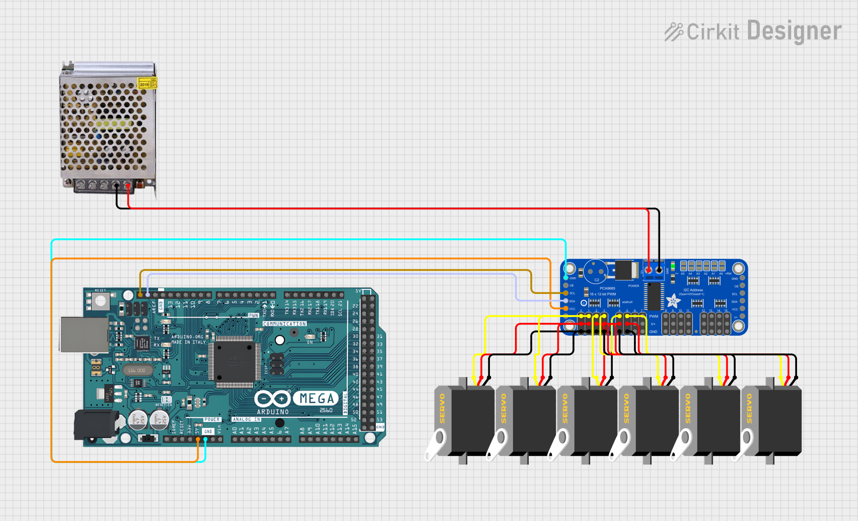
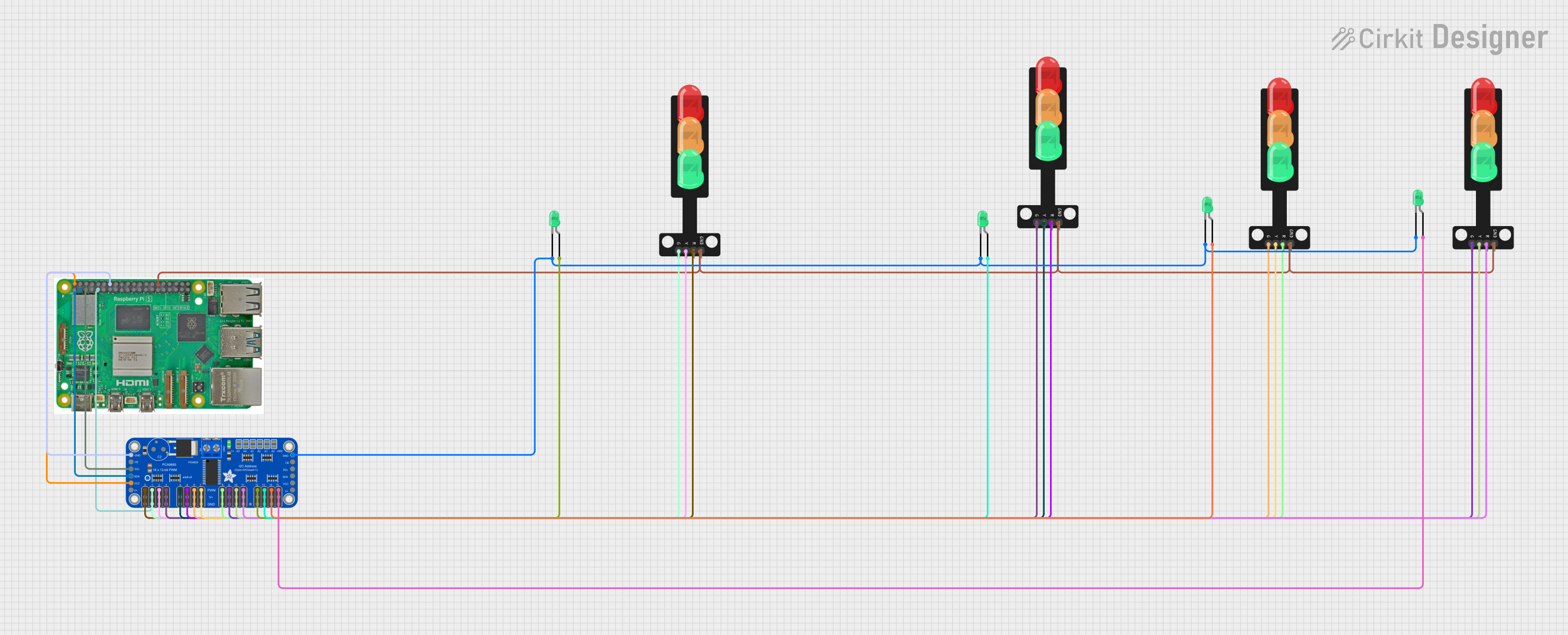
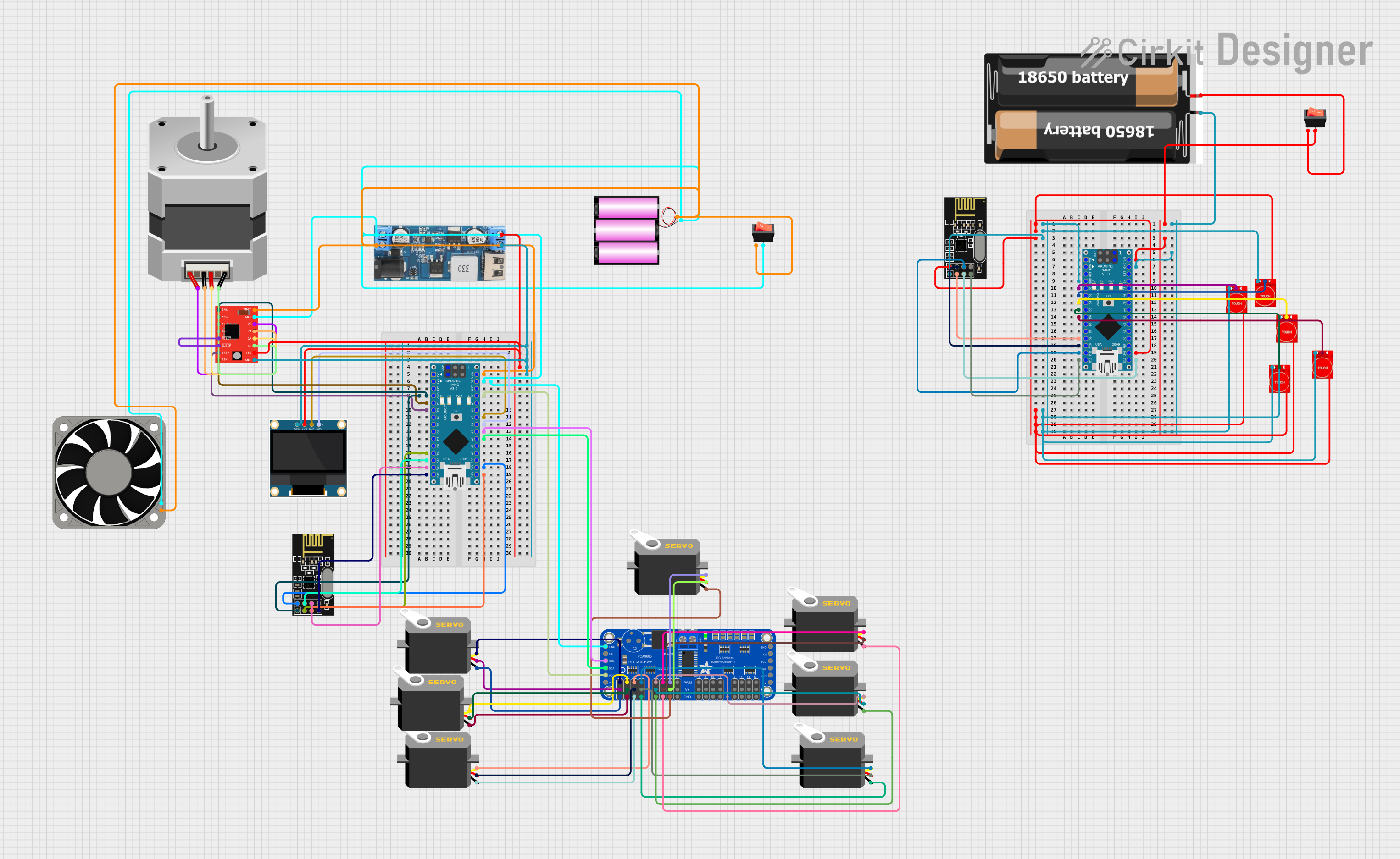
Explore Projects Built with Adafruit 24-Channel 12-bit PWM LED Driver - SPI
Technical Specifications
Key Technical Details
- Channels: 24 independently controllable
- Resolution: 12-bit (4096 levels) per channel
- Voltage: 5V to 6V input
- Output Current: 17 mA per channel (constant-current sink)
- Communication: SPI interface
- Clock Speed: Up to 10 MHz
Pin Configuration and Descriptions
| Pin Number | Name | Description |
|---|---|---|
| 1 | GND | Ground connection |
| 2 | V+ | Power supply (5V-6V) |
| 3 | SCLK | Serial Clock for SPI |
| 4 | MOSI | Master Out Slave In for SPI data |
| 5 | LATCH | Latch pin to update outputs |
| 6 | OE | Output Enable (active low) |
| 7-30 | OUT0-OUT23 | Output pins for each of the 24 channels |
Usage Instructions
Connecting to a Circuit
- Connect the GND pin to the ground of your power supply and microcontroller.
- Connect the V+ pin to a 5V-6V power supply.
- Connect the SCLK, MOSI, and LATCH pins to the corresponding SPI pins on your microcontroller.
- Connect the OE pin to a digital pin on your microcontroller if you wish to use the output enable feature.
- Connect each OUT pin to the anode of an LED, and connect the cathode of the LEDs to ground.
Best Practices
- Use a common ground for the LED driver and microcontroller.
- Ensure that the power supply can handle the cumulative current draw of all connected LEDs.
- Use resistors with LEDs if the forward voltage is less than the supply voltage to prevent damage.
- Avoid connecting LEDs with significantly different forward voltages/currents to the same driver channel.
Example Code for Arduino UNO
#include <SPI.h>

// Define the SPI pins for Arduino UNO
#define LATCH_PIN 10
#define OE_PIN    9

void setup() {
  // Set the latch and output enable pins as outputs
  pinMode(LATCH_PIN, OUTPUT);
  pinMode(OE_PIN, OUTPUT);

  // Begin SPI communication
  SPI.begin();

  // Set output enable to low (enable outputs)
  digitalWrite(OE_PIN, LOW);
}

void loop() {
  // Example: Set all channels to mid brightness
  for (int i = 0; i < 24; i++) {
    sendPWM(i, 2048); // 2048 is half of 4096 (mid brightness)
  }

  // Latch the PWM values to update the outputs
  latchPWM();

  // A delay to see the change in brightness
  delay(1000);
}

void sendPWM(int channel, int value) {
  // Ensure the value is within 12-bit range
  value = value & 0xFFF;

  // Calculate the command byte and the two data bytes
  byte command = 0b11100000 | (channel >> 4);
  byte data1 = (channel << 4) | (value >> 8);
  byte data2 = value & 0xFF;

  // Send the bytes via SPI
  SPI.transfer(command);
  SPI.transfer(data1);
  SPI.transfer(data2);
}

void latchPWM() {
  // Pulse the latch pin to update the LED outputs
  digitalWrite(LATCH_PIN, HIGH);
  delayMicroseconds(10); // Short pulse
  digitalWrite(LATCH_PIN, LOW);
}
Troubleshooting and FAQs
Common Issues
- LEDs are not lighting up: Check the wiring, ensure the power supply is connected and within the correct voltage range, and verify that the OE pin is set to low.
- LEDs are too dim or too bright: Adjust the PWM values in the code to set the desired brightness level. Ensure that the LEDs are connected correctly and that any necessary current-limiting resistors are in place.
- SPI communication errors: Ensure that the SPI pins are connected correctly and that there are no loose connections. Check that the SPI clock speed is compatible with the LED driver.
Solutions and Tips
- Use a multimeter to check for proper voltage levels at the V+ and OUT pins.
- If using multiple LED drivers, ensure that each LATCH pin is controlled separately to update each driver individually.
- For complex troubleshooting, use an oscilloscope to check the SPI signals and verify that the correct data is being sent.
FAQs
Q: Can I chain multiple LED drivers together? A: Yes, you can chain multiple drivers by connecting the MOSI out of the first driver to the MOSI in of the next driver, and so on. Each driver will need its own LATCH pin control.
Q: What is the maximum number of LEDs I can control with this driver? A: You can control up to 24 LEDs with a single driver. However, by chaining multiple drivers, you can control more LEDs.
Q: Can I use this driver with a 3.3V microcontroller? A: While the driver itself requires a 5V-6V supply, logic level converters can be used to interface with 3.3V logic levels on the control pins.