How to Use Phantom Power Circuit: Examples, Pinouts, and Specs
Introduction
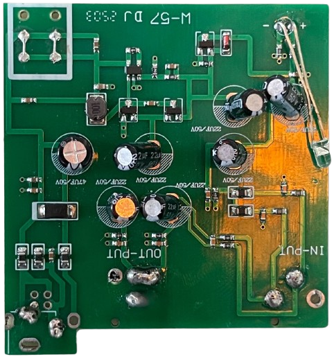
The Phantom Power Circuit is an electronic component designed to supply a DC voltage, typically 48V, to power condenser microphones and other audio equipment. This voltage is delivered through standard microphone cables, allowing the microphone to operate without requiring an external power source. Phantom power is essential in professional audio setups, including recording studios, live sound systems, and broadcasting environments.
Explore Projects Built with Phantom Power Circuit


Explore Projects Built with Phantom Power Circuit
Common Applications and Use Cases
- Powering condenser microphones in professional audio setups.
- Supplying power to active direct boxes (DI boxes) for audio signal balancing.
- Used in audio interfaces, mixers, and preamplifiers to enable high-quality sound capture.
- Supporting audio equipment in live performances, podcasting, and studio recording.
Technical Specifications
Below are the key technical details and pin configurations for a typical Phantom Power Circuit:
Key Technical Details
| Parameter | Value |
|---|---|
| Input Voltage | 12V to 48V DC |
| Output Voltage | 48V DC (standard phantom power) |
| Current Rating | 10mA to 14mA per microphone |
| Connector Type | XLR (3-pin) |
| Power Regulation | Linear or switching regulator |
| Protection Features | Overcurrent and short-circuit |
Pin Configuration and Descriptions
XLR Connector Pinout
| Pin Number | Name | Description |
|---|---|---|
| 1 | Ground (GND) | Common ground for the circuit and microphone. |
| 2 | Signal (+) | Carries the positive audio signal and phantom power. |
| 3 | Signal (-) | Carries the negative audio signal and phantom power. |
Internal Circuit Connections
| Component | Description |
|---|---|
| Resistors (6.8kΩ) | Limit current to the microphone. |
| Capacitors | Block DC voltage from interfering with audio signals. |
| Voltage Regulator | Ensures stable 48V output. |
Usage Instructions
How to Use the Phantom Power Circuit in a Setup
- Connect the Circuit to a Power Source: Ensure the input voltage matches the circuit's requirements (e.g., 12V to 48V DC).
- Connect the Microphone: Plug the condenser microphone into the XLR input of the phantom power circuit.
- Connect to Audio Equipment: Use an XLR cable to connect the output of the phantom power circuit to a mixer, audio interface, or preamplifier.
- Power On the Circuit: Turn on the power supply to activate the phantom power circuit.
Important Considerations and Best Practices
- Check Compatibility: Ensure the microphone or audio equipment is designed to work with 48V phantom power.
- Avoid Dynamic Microphones: Do not use phantom power with ribbon or dynamic microphones unless they explicitly support it, as it may damage the microphone.
- Use Quality Cables: Use balanced XLR cables to minimize noise and interference.
- Protect Against Short Circuits: Ensure proper wiring and connections to prevent damage to the circuit or connected devices.
Example: Using Phantom Power with an Arduino UNO
While the Phantom Power Circuit is not directly connected to an Arduino UNO, you can use the Arduino to monitor or control the circuit. Below is an example of using an Arduino to monitor the 48V output voltage:
// Example code to monitor phantom power voltage using Arduino UNO
// Connect the output of a voltage divider to an analog pin (e.g., A0)

// Define the analog pin for voltage monitoring
const int voltagePin = A0;

// Define the voltage divider ratio (e.g., R1 = 100kΩ, R2 = 10kΩ)
const float voltageDividerRatio = 11.0;

void setup() {
  Serial.begin(9600); // Initialize serial communication
  pinMode(voltagePin, INPUT); // Set the voltage pin as input
}

void loop() {
  int analogValue = analogRead(voltagePin); // Read the analog value
  float voltage = (analogValue * 5.0 / 1023.0) * voltageDividerRatio;
  // Convert the analog value to the actual voltage using the divider ratio

  Serial.print("Phantom Power Voltage: ");
  Serial.print(voltage);
  Serial.println(" V");

  delay(1000); // Wait for 1 second before the next reading
}
Notes:
- Use a voltage divider to step down the 48V to a safe range for the Arduino's analog input (0-5V).
- Ensure proper isolation between the phantom power circuit and the Arduino to avoid damage.
Troubleshooting and FAQs
Common Issues and Solutions
| Issue | Possible Cause | Solution |
|---|---|---|
| No power to the microphone | Faulty power supply or wiring | Check the power source and connections. |
| Microphone produces noise or hum | Poor cable quality or interference | Use shielded XLR cables and check grounding. |
| Phantom power not detected | Incorrect circuit configuration | Verify resistor and capacitor values. |
| Microphone not working | Incompatible microphone type | Ensure the microphone supports phantom power. |
FAQs
Can I use phantom power with dynamic microphones?
- Phantom power is not required for dynamic microphones and may damage ribbon microphones. Always check the microphone's specifications.
What happens if I connect a device that doesn't need phantom power?
- Most modern audio equipment is designed to ignore phantom power if not required, but always verify compatibility to avoid damage.
How do I test if the phantom power circuit is working?
- Use a multimeter to measure the voltage across pins 2 and 3 of the XLR connector. It should read approximately 48V.
Can I use phantom power with unbalanced cables?
- No, phantom power requires balanced XLR cables to function correctly and avoid interference.
By following this documentation, you can effectively use and troubleshoot a Phantom Power Circuit in your audio setup.