How to Use ESP32-C6-DEV-KIT-N8: Examples, Pinouts, and Specs
Introduction
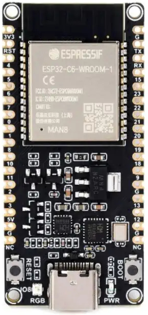
The ESP32-C6-DEV-KIT-N8 is a development board manufactured by Waveshare, featuring the ESP32-C6 chip. This board is designed for IoT applications and prototyping, offering integrated Wi-Fi 6, Bluetooth 5.0 Low Energy (LE), and IEEE 802.15.4 (Thread/Zigbee) connectivity. Its compact design and versatile features make it ideal for developers working on smart home devices, industrial IoT, and wireless communication projects.
Explore Projects Built with ESP32-C6-DEV-KIT-N8


Explore Projects Built with ESP32-C6-DEV-KIT-N8
Common Applications and Use Cases
- Smart home automation systems
- Industrial IoT devices
- Wireless sensor networks
- Prototyping for Zigbee or Thread-based applications
- Low-power Bluetooth communication projects
- Wi-Fi-enabled data logging and monitoring systems
Technical Specifications
The following table outlines the key technical details of the ESP32-C6-DEV-KIT-N8:
| Parameter | Specification |
|---|---|
| Chipset | ESP32-C6 |
| Wireless Connectivity | Wi-Fi 6 (802.11ax), Bluetooth 5.0 LE, IEEE 802.15.4 (Thread/Zigbee) |
| Processor | 32-bit RISC-V single-core processor, up to 160 MHz |
| Flash Memory | 8 MB |
| SRAM | 512 KB |
| GPIO Pins | 22 (multipurpose, including ADC, PWM, I2C, SPI, UART) |
| Operating Voltage | 3.3V |
| Power Supply | USB Type-C (5V input) |
| Dimensions | 51 mm x 25.4 mm |
| Operating Temperature | -40°C to 85°C |
Pin Configuration and Descriptions
The ESP32-C6-DEV-KIT-N8 features a 22-pin GPIO layout. Below is the pin configuration:
| Pin Number | Pin Name | Function | Description |
|---|---|---|---|
| 1 | GND | Ground | Common ground for the board |
| 2 | 3V3 | Power | 3.3V power output |
| 3 | EN | Enable | Chip enable (active high) |
| 4 | IO0 | GPIO0 | General-purpose I/O, boot mode selection |
| 5 | IO1 | GPIO1 | General-purpose I/O |
| 6 | IO2 | GPIO2 | General-purpose I/O |
| 7 | IO3 | GPIO3 | General-purpose I/O |
| 8 | IO4 | GPIO4 | General-purpose I/O |
| 9 | IO5 | GPIO5 | General-purpose I/O |
| 10 | IO6 | GPIO6 | General-purpose I/O |
| 11 | IO7 | GPIO7 | General-purpose I/O |
| 12 | IO8 | GPIO8 | General-purpose I/O |
| 13 | IO9 | GPIO9 | General-purpose I/O |
| 14 | IO10 | GPIO10 | General-purpose I/O |
| 15 | IO11 | GPIO11 | General-purpose I/O |
| 16 | IO12 | GPIO12 | General-purpose I/O |
| 17 | IO13 | GPIO13 | General-purpose I/O |
| 18 | IO14 | GPIO14 | General-purpose I/O |
| 19 | IO15 | GPIO15 | General-purpose I/O |
| 20 | IO16 | GPIO16 | General-purpose I/O |
| 21 | IO17 | GPIO17 | General-purpose I/O |
| 22 | IO18 | GPIO18 | General-purpose I/O |
Usage Instructions
How to Use the ESP32-C6-DEV-KIT-N8 in a Circuit
- Powering the Board: Connect the board to a computer or power source using a USB Type-C cable. Ensure the power supply provides 5V.
- Programming the Board: Use the Arduino IDE or ESP-IDF (Espressif IoT Development Framework) to program the board. Install the necessary drivers and libraries for ESP32-C6.
- Connecting Peripherals: Use the GPIO pins to connect sensors, actuators, or other peripherals. Refer to the pin configuration table for specific pin functions.
- Uploading Code: Compile and upload your code to the board via the USB connection. Ensure the correct COM port and board type are selected in your development environment.
Important Considerations and Best Practices
- Voltage Levels: The GPIO pins operate at 3.3V. Avoid applying higher voltages to prevent damage.
- Boot Mode: To enter bootloader mode, hold the IO0 pin low while resetting the board.
- Wi-Fi and Bluetooth Antenna: Ensure the onboard antenna is not obstructed for optimal wireless performance.
- Power Supply: Use a stable 5V power source to avoid unexpected resets or instability.
Example Code for Arduino UNO Integration
Below is an example of using the ESP32-C6-DEV-KIT-N8 to read data from a DHT11 temperature and humidity sensor and send it to a serial monitor:
#include <DHT.h>

// Define the DHT sensor pin and type
#define DHTPIN 4 // GPIO4 is connected to the DHT11 data pin
#define DHTTYPE DHT11

DHT dht(DHTPIN, DHTTYPE);

void setup() {
  Serial.begin(115200); // Initialize serial communication at 115200 baud
  dht.begin();          // Initialize the DHT sensor
  Serial.println("DHT11 Sensor Test");
}

void loop() {
  delay(2000); // Wait 2 seconds between readings

  float humidity = dht.readHumidity();    // Read humidity
  float temperature = dht.readTemperature(); // Read temperature in Celsius

  // Check if the readings are valid
  if (isnan(humidity) || isnan(temperature)) {
    Serial.println("Failed to read from DHT sensor!");
    return;
  }

  // Print the readings to the serial monitor
  Serial.print("Humidity: ");
  Serial.print(humidity);
  Serial.print("%  Temperature: ");
  Serial.print(temperature);
  Serial.println("°C");
}
Troubleshooting and FAQs
Common Issues Users Might Face
Board Not Detected by Computer:
- Ensure the USB cable is functional and supports data transfer.
- Install the correct USB-to-serial drivers for the ESP32-C6.
Code Upload Fails:
- Verify the correct COM port and board type are selected in the IDE.
- Check if the board is in bootloader mode (hold IO0 low during reset).
Wi-Fi or Bluetooth Connectivity Issues:
- Ensure the onboard antenna is unobstructed.
- Verify the network credentials or Bluetooth pairing settings in your code.
Unstable Operation:
- Use a stable 5V power source.
- Avoid exceeding the GPIO voltage limits (3.3V).
Solutions and Tips for Troubleshooting
- Reset the Board: Press the reset button to restart the board and clear temporary issues.
- Check Connections: Ensure all peripheral connections are secure and correctly wired.
- Update Firmware: Use the latest ESP-IDF or Arduino core for ESP32 to ensure compatibility and bug fixes.
- Debugging: Use the serial monitor to print debug messages and identify issues in your code.
By following this documentation, users can effectively utilize the ESP32-C6-DEV-KIT-N8 for their IoT and prototyping projects.