
How to Use 3.5mm Audio Jack: Examples, Pinouts, and Specs
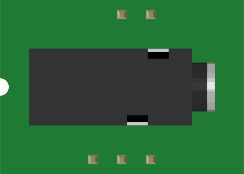
 Design with 3.5mm Audio Jack in Cirkit Designer
Introduction
- The 3.5mm audio jack is a widely used standard connector for transmitting audio signals. It is commonly found in devices such as headphones, speakers, smartphones, laptops, and audio equipment.
- This component is versatile and supports stereo and mono audio signals, as well as microphone input in some configurations. Its compact size and ease of use make it a popular choice for audio connectivity.
Explore Projects Built with 3.5mm Audio Jack
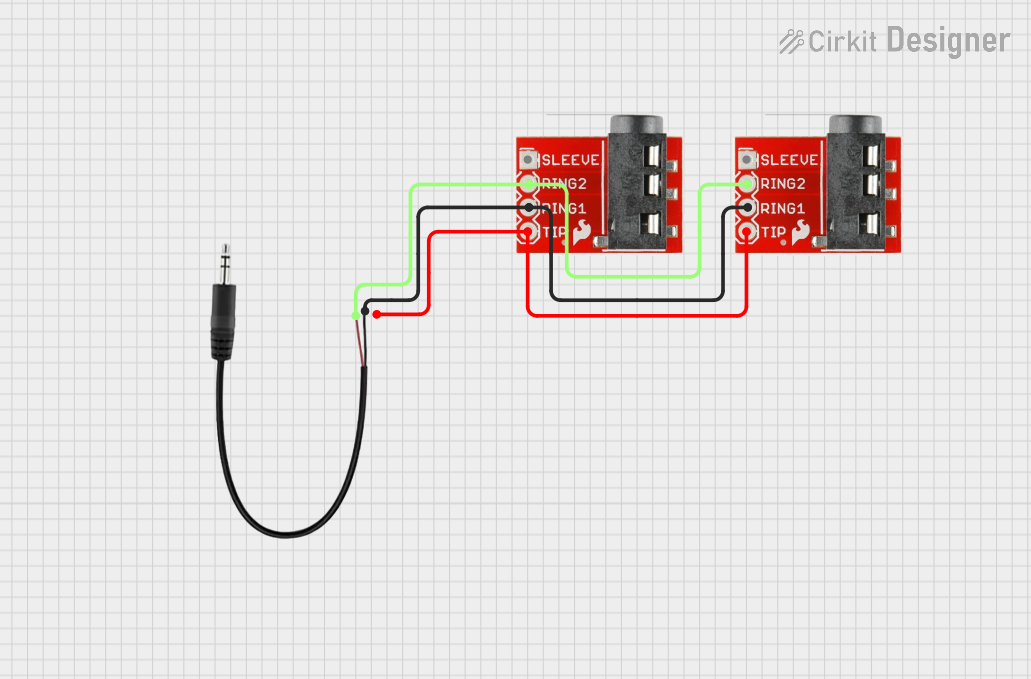 Open Project in Cirkit Designer
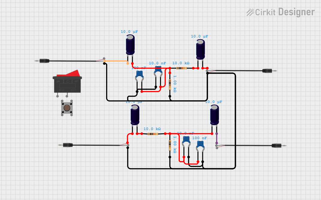 Open Project in Cirkit Designer
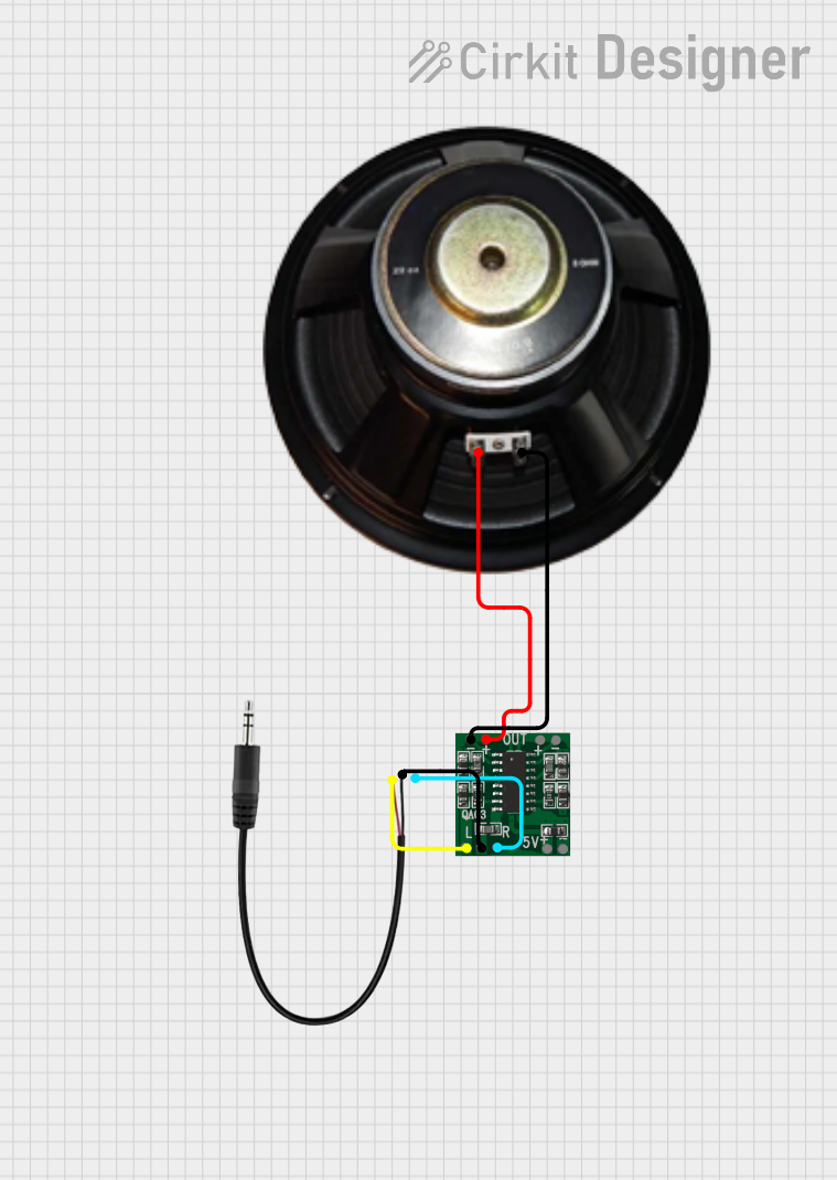 Open Project in Cirkit Designer
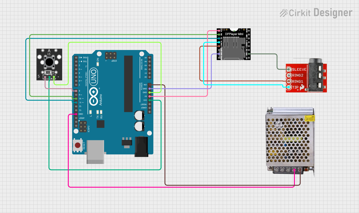 Open Project in Cirkit Designer
Explore Projects Built with 3.5mm Audio Jack
Open Project in Cirkit DesignerOpen Project in Cirkit DesignerOpen Project in Cirkit DesignerOpen Project in Cirkit DesignerTechnical Specifications
- Connector Type: 3.5mm TRS (Tip-Ring-Sleeve) or TRRS (Tip-Ring-Ring-Sleeve)
- Supported Signals: Stereo audio, mono audio, microphone input (TRRS)
- Voltage Rating: Typically up to 5V (signal level)
- Current Rating: Low current, typically in the milliampere range
- Material: Metal contacts (gold or nickel-plated) with plastic or metal housing
- Mounting Style: Through-hole or surface-mount (depending on the model)
Pin Configuration and Descriptions
The pin configuration of a 3.5mm audio jack depends on its type (TRS or TRRS). Below are the details:
TRS (Tip-Ring-Sleeve) Configuration
| Pin Name | Description | Signal Type |
|---|---|---|
| Tip | Left audio channel | Analog signal |
| Ring | Right audio channel | Analog signal |
| Sleeve | Ground (common return path) | Ground connection |
TRRS (Tip-Ring-Ring-Sleeve) Configuration
| Pin Name | Description | Signal Type |
|---|---|---|
| Tip | Left audio channel | Analog signal |
| Ring 1 | Right audio channel | Analog signal |
| Ring 2 | Microphone input or ground | Analog signal/GND |
| Sleeve | Ground (common return path) | Ground connection |
Note: The exact pinout for TRRS jacks may vary depending on the standard used (e.g., CTIA or OMTP). Always verify the pinout for your specific application.
Usage Instructions
How to Use the Component in a Circuit
- Identify the Pinout: Determine whether your 3.5mm audio jack is TRS or TRRS and identify the corresponding pins.
- Connect to Audio Source:
- For TRS: Connect the Tip and Ring to the left and right audio channels, respectively, and the Sleeve to ground.
- For TRRS: Connect the additional Ring (Ring 2) to the microphone input or ground, depending on the standard.
- Soldering: If using a through-hole jack, solder the pins to a PCB. For surface-mount jacks, ensure proper alignment and soldering.
- Use with Microcontrollers: To interface with a microcontroller (e.g., Arduino), use an audio amplifier circuit to process the audio signals, as microcontrollers cannot directly handle analog audio signals.
Important Considerations and Best Practices
- Signal Integrity: Use shielded cables to minimize noise and interference in audio signals.
- Compatibility: Verify the pinout standard (CTIA or OMTP) when using TRRS jacks to ensure compatibility with your device.
- Mechanical Stress: Avoid excessive force on the jack to prevent damage to the connector or PCB.
- Amplification: Use an appropriate amplifier circuit if the audio signal needs to be processed or amplified.
Example: Connecting a 3.5mm Audio Jack to an Arduino UNO
Below is an example of how to read audio signals from a 3.5mm jack using an Arduino UNO. This example assumes the use of an external audio amplifier circuit to condition the signal.
// Example: Reading audio signal from a 3.5mm audio jack
// Note: Use an external amplifier circuit to condition the audio signal
// before connecting it to the Arduino's analog input pin.

const int audioPin = A0; // Analog pin to read the audio signal

void setup() {
  Serial.begin(9600); // Initialize serial communication
  pinMode(audioPin, INPUT); // Set the audio pin as input
}

void loop() {
  int audioValue = analogRead(audioPin); // Read the audio signal
  Serial.println(audioValue); // Print the signal value to the Serial Monitor
  delay(10); // Small delay for stability
}
Warning: Directly connecting a 3.5mm audio jack to an Arduino without proper signal conditioning may damage the microcontroller or result in inaccurate readings.
Troubleshooting and FAQs
Common Issues Users Might Face
No Audio Output:
- Cause: Incorrect pin connections or damaged cable.
- Solution: Verify the pinout and ensure proper soldering or cable connections.
Noise or Interference:
- Cause: Unshielded cables or poor grounding.
- Solution: Use shielded cables and ensure a solid ground connection.
Incompatible Microphone Input:
- Cause: Mismatch between CTIA and OMTP standards.
- Solution: Use an adapter or rewire the connections to match the required standard.
Loose Connection:
- Cause: Worn-out or poorly mounted jack.
- Solution: Replace the jack or ensure it is securely mounted.
Solutions and Tips for Troubleshooting
- Test with a Multimeter: Check continuity between the pins and the connected device to ensure proper connections.
- Inspect for Damage: Look for physical damage to the jack or solder joints.
- Use a Breakout Board: For prototyping, use a 3.5mm audio jack breakout board to simplify connections and testing.
By following this documentation, you can effectively use a 3.5mm audio jack in your projects and troubleshoot common issues with ease.