How to Use Smartelex 8 channel sensor array : Examples, Pinouts, and Specs
Introduction
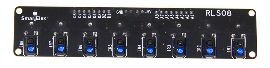
The SmartElex RLS-08 Analog & Digital Line Sensor Array, manufactured by Robu, is a versatile sensor array with 8 channels designed for detecting and measuring various environmental parameters. This component is commonly used in robotics and automation systems for precise data collection, such as line following robots, edge detection, and other applications requiring accurate environmental sensing.
Explore Projects Built with Smartelex 8 channel sensor array

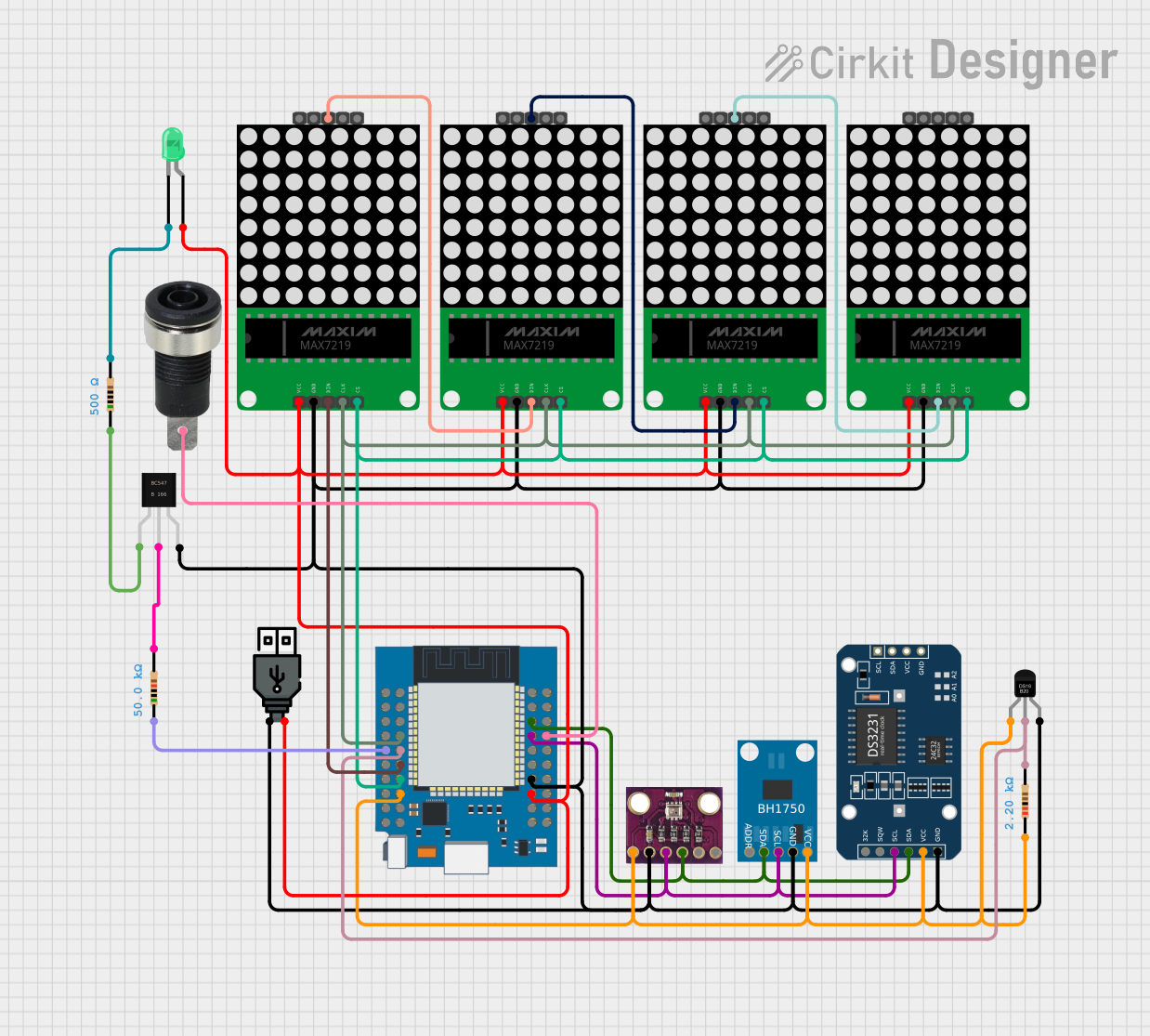

Explore Projects Built with Smartelex 8 channel sensor array
Technical Specifications
Key Technical Details
| Parameter | Value |
|---|---|
| Operating Voltage | 3.3V to 5V |
| Output Type | Analog and Digital |
| Number of Channels | 8 |
| Sensor Type | Infrared (IR) |
| Dimensions | 100mm x 20mm x 10mm |
| Weight | 10g |
| Operating Temperature | -10°C to 50°C |
Pin Configuration and Descriptions
| Pin No. | Pin Name | Description |
|---|---|---|
| 1 | VCC | Power supply (3.3V to 5V) |
| 2 | GND | Ground |
| 3 | A0 | Analog output for sensor 1 |
| 4 | A1 | Analog output for sensor 2 |
| 5 | A2 | Analog output for sensor 3 |
| 6 | A3 | Analog output for sensor 4 |
| 7 | A4 | Analog output for sensor 5 |
| 8 | A5 | Analog output for sensor 6 |
| 9 | A6 | Analog output for sensor 7 |
| 10 | A7 | Analog output for sensor 8 |
| 11 | D0 | Digital output for sensor 1 |
| 12 | D1 | Digital output for sensor 2 |
| 13 | D2 | Digital output for sensor 3 |
| 14 | D3 | Digital output for sensor 4 |
| 15 | D4 | Digital output for sensor 5 |
| 16 | D5 | Digital output for sensor 6 |
| 17 | D6 | Digital output for sensor 7 |
| 18 | D7 | Digital output for sensor 8 |
Usage Instructions
How to Use the Component in a Circuit
- Power Supply: Connect the VCC pin to a 3.3V or 5V power supply and the GND pin to the ground of your circuit.
- Analog Outputs: Connect the analog output pins (A0 to A7) to the analog input pins of your microcontroller or ADC (Analog-to-Digital Converter).
- Digital Outputs: Connect the digital output pins (D0 to D7) to the digital input pins of your microcontroller.
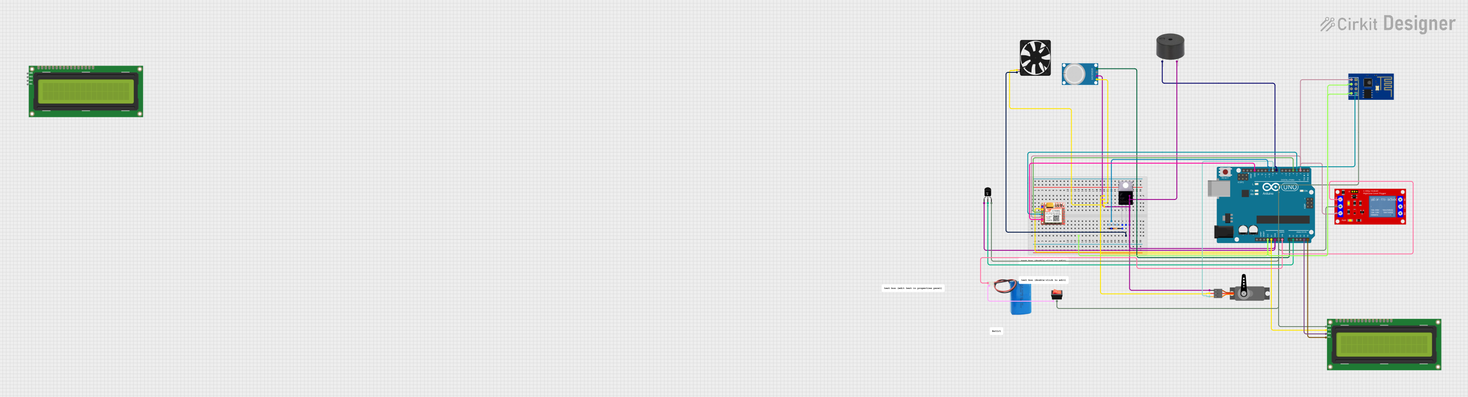
Example Circuit with Arduino UNO
- VCC -> 5V
- GND -> GND
- A0 -> A0 (Arduino)
- A1 -> A1 (Arduino)
- A2 -> A2 (Arduino)
- A3 -> A3 (Arduino)
- A4 -> A4 (Arduino)
- A5 -> A5 (Arduino)
- A6 -> A6 (Arduino)
- A7 -> A7 (Arduino)
Sample Arduino Code
// Define the analog pins connected to the sensor array
const int sensorPins[8] = {A0, A1, A2, A3, A4, A5, A6, A7};

void setup() {
  Serial.begin(9600); // Initialize serial communication at 9600 baud rate
  for (int i = 0; i < 8; i++) {
    pinMode(sensorPins[i], INPUT); // Set sensor pins as input
  }
}

void loop() {
  for (int i = 0; i < 8; i++) {
    int sensorValue = analogRead(sensorPins[i]); // Read the analog value
    Serial.print("Sensor ");
    Serial.print(i);
    Serial.print(": ");
    Serial.println(sensorValue); // Print the sensor value to the serial monitor
  }
  delay(500); // Wait for 500 milliseconds before the next reading
}
Important Considerations and Best Practices
- Power Supply: Ensure that the power supply voltage is within the specified range (3.3V to 5V) to avoid damaging the sensor array.
- Calibration: Calibrate the sensors for your specific application to achieve accurate readings.
- Interference: Avoid placing the sensor array near sources of infrared interference, such as direct sunlight or other IR-emitting devices.
Troubleshooting and FAQs
Common Issues Users Might Face
No Output from Sensors:
- Solution: Check the power supply connections and ensure that the VCC and GND pins are properly connected.
Inconsistent Readings:
- Solution: Ensure that the sensor array is properly calibrated and that there are no sources of interference nearby.
Sensor Values Not Changing:
- Solution: Verify that the sensors are not obstructed and that they are positioned correctly for the intended application.
FAQs
Can I use the sensor array with a 3.3V microcontroller?
- Yes, the sensor array can operate with a power supply voltage of 3.3V to 5V.
How do I calibrate the sensors?
- Calibration involves adjusting the sensor readings to match the specific conditions of your application. This can be done through software by setting threshold values based on the sensor outputs.
What is the maximum distance the sensors can detect?
- The detection range depends on the reflectivity of the surface and the ambient lighting conditions. Typically, the sensors can detect objects within a few centimeters.
By following this documentation, users can effectively integrate and utilize the SmartElex RLS-08 Analog & Digital Line Sensor Array in their projects, ensuring accurate and reliable environmental sensing.