Cirkit Designer Logo
Cirkit Designer
Your all-in-one circuit design IDE
Home / 
Component Documentation

How to Use 2ch relay: Examples, Pinouts, and Specs

Image of 2ch relay
Cirkit Designer LogoDesign with 2ch relay in Cirkit Designer

Introduction

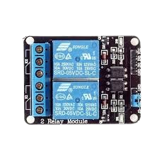
A 2-channel relay module is an electronic device that allows a low-power signal to control two separate high-power circuits. It acts as an electrically operated switch and is commonly used in automation systems, where it is necessary to control devices like motors, lights, and other appliances. Each channel on the relay can be controlled independently, allowing for versatile control schemes in various applications.

Explore Projects Built with 2ch relay

Use Cirkit Designer to design, explore, and prototype these projects online. Some projects support real-time simulation. Click "Open Project" to start designing instantly!
Wi-Fi Controlled Smart Relay Switch with ESP8266 and MCP23017
Image of Bed Room: A project utilizing 2ch relay in a practical application
This circuit is designed to control an 8-channel relay module via an ESP8266 microcontroller, which interfaces with an MCP23017 I/O expander over I2C. The ESP8266 connects to a WiFi network and subscribes to MQTT topics to receive commands for toggling the relays. Additionally, there are toggle switches connected to the MCP23017 that allow manual control of the relays, with the system's state being reported back via MQTT.
Cirkit Designer LogoOpen Project in Cirkit Designer
WeMos D1 R2 Controlled Relay Switching Circuit for AC Bulb and USB Charger
Image of Hand Gesture Light: A project utilizing 2ch relay in a practical application
This circuit uses a WeMos D1 R2 microcontroller to control a 5V 2-relay module, which in turn controls the power to an AC bulb and a cellphone charger. The microcontroller also interfaces with a line tracking sensor, which likely provides input to control the relay states. The AC bulb and cellphone charger are powered by an AC wire connection, with the relay acting as a switch for the bulb.
Cirkit Designer LogoOpen Project in Cirkit Designer
Wi-Fi Controlled 4-Channel Relay System with Arduino and ESP8266
Image of Wi-Fi Controlled 4-Channel Relay with Arduino and ESP8266: A project utilizing 2ch relay in a practical application
This circuit is a Wi-Fi controlled 4-channel relay system using an Arduino UNO and an ESP8266 module. The relays can be controlled via a web interface served by the ESP8266, and the status of each relay is displayed on a 16x4 I2C LCD. The relays are used to control four 220V AC red lights, and the Arduino communicates with the ESP8266 via serial communication.
Cirkit Designer LogoOpen Project in Cirkit Designer
Wi-Fi Controlled Relay Module with ESP8266 and MCP23017
Image of smart home: A project utilizing 2ch relay in a practical application
This circuit is a WiFi-enabled relay control system using an ESP8266-01 module and an MCP23017 I/O expander. The ESP8266 communicates with the MCP23017 via I2C to control an 8-channel relay module based on the state of 8 rocker switches, allowing for remote and manual control of connected devices.
Cirkit Designer LogoOpen Project in Cirkit Designer

Explore Projects Built with 2ch relay

Use Cirkit Designer to design, explore, and prototype these projects online. Some projects support real-time simulation. Click "Open Project" to start designing instantly!
Image of Bed Room: A project utilizing 2ch relay in a practical application
Wi-Fi Controlled Smart Relay Switch with ESP8266 and MCP23017
This circuit is designed to control an 8-channel relay module via an ESP8266 microcontroller, which interfaces with an MCP23017 I/O expander over I2C. The ESP8266 connects to a WiFi network and subscribes to MQTT topics to receive commands for toggling the relays. Additionally, there are toggle switches connected to the MCP23017 that allow manual control of the relays, with the system's state being reported back via MQTT.
Cirkit Designer LogoOpen Project in Cirkit Designer
Image of Hand Gesture Light: A project utilizing 2ch relay in a practical application
WeMos D1 R2 Controlled Relay Switching Circuit for AC Bulb and USB Charger
This circuit uses a WeMos D1 R2 microcontroller to control a 5V 2-relay module, which in turn controls the power to an AC bulb and a cellphone charger. The microcontroller also interfaces with a line tracking sensor, which likely provides input to control the relay states. The AC bulb and cellphone charger are powered by an AC wire connection, with the relay acting as a switch for the bulb.
Cirkit Designer LogoOpen Project in Cirkit Designer
Image of Wi-Fi Controlled 4-Channel Relay with Arduino and ESP8266: A project utilizing 2ch relay in a practical application
Wi-Fi Controlled 4-Channel Relay System with Arduino and ESP8266
This circuit is a Wi-Fi controlled 4-channel relay system using an Arduino UNO and an ESP8266 module. The relays can be controlled via a web interface served by the ESP8266, and the status of each relay is displayed on a 16x4 I2C LCD. The relays are used to control four 220V AC red lights, and the Arduino communicates with the ESP8266 via serial communication.
Cirkit Designer LogoOpen Project in Cirkit Designer
Image of smart home: A project utilizing 2ch relay in a practical application
Wi-Fi Controlled Relay Module with ESP8266 and MCP23017
This circuit is a WiFi-enabled relay control system using an ESP8266-01 module and an MCP23017 I/O expander. The ESP8266 communicates with the MCP23017 via I2C to control an 8-channel relay module based on the state of 8 rocker switches, allowing for remote and manual control of connected devices.
Cirkit Designer LogoOpen Project in Cirkit Designer

Common Applications and Use Cases

  • Home automation (e.g., controlling lights, fans, and other home appliances)
  • Industrial controls (e.g., starting/stopping motors, opening/closing valves)
  • Automotive electronics (e.g., controlling headlights, alarm systems)
  • Robotics (e.g., actuating motors or solenoids)

Technical Specifications

Key Technical Details

  • Operating Voltage (Vcc): 5V DC
  • Trigger Voltage: Typically 3.3V to 5V DC
  • Switching Voltage: Up to 250V AC or 30V DC
  • Switching Current: Up to 10A per channel
  • Isolation: Opto-isolated inputs

Pin Configuration and Descriptions

Pin Name Description
VCC Connect to 5V power supply
GND Connect to ground
IN1 Control signal for relay channel 1
IN2 Control signal for relay channel 2
NO1 Normally open contact for relay channel 1
COM1 Common contact for relay channel 1
NC1 Normally closed contact for relay channel 1
NO2 Normally open contact for relay channel 2
COM2 Common contact for relay channel 2
NC2 Normally closed contact for relay channel 2

Usage Instructions

How to Use the Component in a Circuit

  1. Powering the Module:

    • Connect the VCC pin to a 5V power supply.
    • Connect the GND pin to the ground of the power supply.
  2. Connecting the Control Signal:

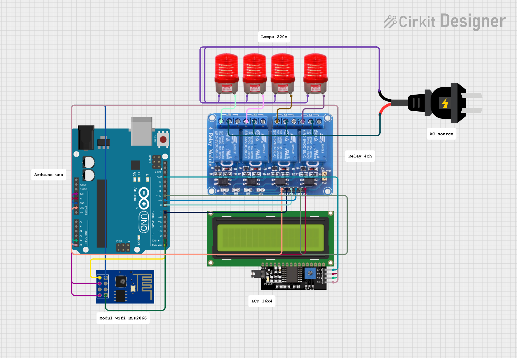
    • Connect the IN1 and IN2 pins to the digital outputs of a microcontroller, such as an Arduino UNO.
  3. Connecting the Load:

    • For each channel, connect the device you want to control between the common (COM) and normally open (NO) contacts if you want the device to be off when the relay is not energized.
    • Use the normally closed (NC) contact if you want the device to be on when the relay is not energized.

Important Considerations and Best Practices

  • Ensure that the power ratings of the relay match the requirements of the load you are controlling.
  • Always consider the safety implications when working with high voltage and/or current.
  • Use flyback diodes across inductive loads to prevent back EMF damage.
  • Avoid running high-voltage wires close to low-voltage control wires to minimize interference.

Example Code for Arduino UNO

// Define relay control pins
#define RELAY1_PIN  7
#define RELAY2_PIN  8

void setup() {
  // Set relay pins as outputs
  pinMode(RELAY1_PIN, OUTPUT);
  pinMode(RELAY2_PIN, OUTPUT);
}

void loop() {
  // Turn on relay channel 1
  digitalWrite(RELAY1_PIN, HIGH);
  delay(1000); // Wait for 1 second
  
  // Turn off relay channel 1
  digitalWrite(RELAY1_PIN, LOW);
  delay(1000); // Wait for 1 second
  
  // Turn on relay channel 2
  digitalWrite(RELAY2_PIN, HIGH);
  delay(1000); // Wait for 1 second
  
  // Turn off relay channel 2
  digitalWrite(RELAY2_PIN, LOW);
  delay(1000); // Wait for 1 second
}

Troubleshooting and FAQs

Common Issues Users Might Face

  • Relay does not switch: Check the control signal voltage and connections.
  • Intermittent operation: Ensure solid connections and that the power supply can handle the current draw.
  • Noise issues: Use shielded cables for high-voltage connections and keep them away from low-voltage control lines.

Solutions and Tips for Troubleshooting

  • Verify that the power supply voltage and current ratings are adequate.
  • Check for proper wiring of the control signal, power supply, and load.
  • Ensure that the load does not exceed the relay's maximum voltage and current ratings.
  • If the relay is not responding to the control signal, check the microcontroller's code and connections.

FAQs

Q: Can I control the 2-channel relay module with a 3.3V microcontroller? A: Yes, most 2-channel relay modules can be triggered with a 3.3V signal.

Q: Is it necessary to use a separate power supply for the relay module? A: It depends on the current requirements of the relay coil and the capacity of your microcontroller's power supply. If the relay draws more current than the microcontroller can supply, a separate power source is needed.

Q: Can I use the relay module with AC loads? A: Yes, the relay module can switch AC loads up to the specified voltage and current ratings. Always ensure safety when working with AC circuits.