How to Use 4R7 Voltage Regulator: Examples, Pinouts, and Specs
Introduction
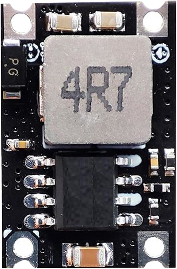
The 4R7 voltage regulator is an essential electronic component designed to maintain a constant and stable output voltage, regardless of fluctuations in input voltage or variations in load conditions. This regulator is commonly used in power supply circuits to ensure the reliable operation of electronic devices by providing a consistent voltage level. Its compact design and efficiency make it ideal for a wide range of applications.
Explore Projects Built with 4R7 Voltage Regulator


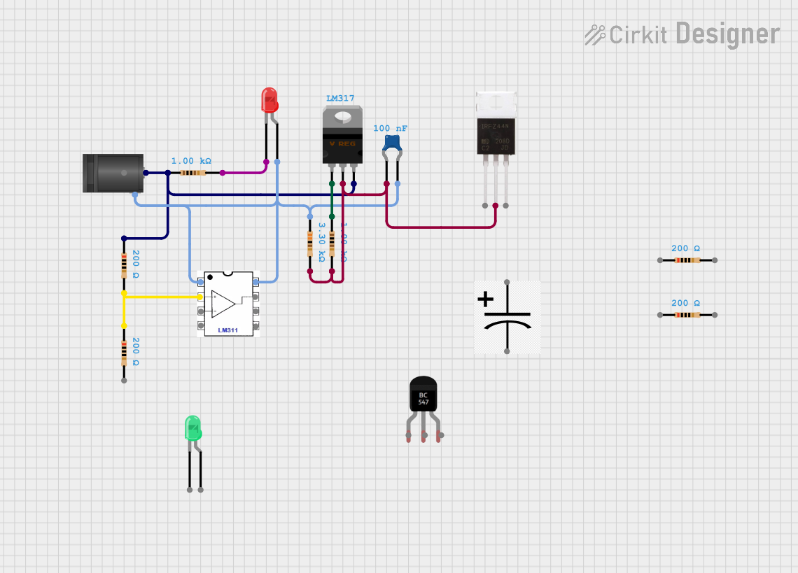
Explore Projects Built with 4R7 Voltage Regulator
Common Applications and Use Cases
- Power supply circuits for microcontrollers and sensors
- Voltage stabilization in battery-powered devices
- Protection of sensitive electronic components from voltage fluctuations
- Use in DC-DC converter circuits
- Embedded systems and IoT devices
Technical Specifications
The 4R7 voltage regulator is designed to deliver stable performance under various conditions. Below are its key technical specifications:
| Parameter | Value |
|---|---|
| Input Voltage Range | 4.5V to 40V |
| Output Voltage | Fixed (e.g., 5V, 3.3V) or adjustable |
| Output Current | Up to 1.5A (depending on model) |
| Dropout Voltage | Typically 1.1V to 2.0V |
| Efficiency | Up to 90% (for switching regulators) |
| Operating Temperature | -40°C to +125°C |
| Package Type | TO-220, SOT-223, or similar |
Pin Configuration and Descriptions
The pin configuration of the 4R7 voltage regulator may vary depending on the specific model and package type. Below is a general pinout for a standard 3-pin linear voltage regulator:
| Pin Number | Pin Name | Description |
|---|---|---|
| 1 | Input (VIN) | Connects to the unregulated input voltage source. |
| 2 | Ground (GND) | Common ground for input and output. |
| 3 | Output (VOUT) | Provides the regulated output voltage. |
Usage Instructions
How to Use the 4R7 Voltage Regulator in a Circuit
Connect the Input Voltage (VIN):
Attach the unregulated DC voltage source to the input pin (VIN). Ensure the input voltage is within the specified range (e.g., 4.5V to 40V).Connect the Ground (GND):
Connect the ground pin of the regulator to the common ground of the circuit.Connect the Output Voltage (VOUT):
Attach the output pin (VOUT) to the load or circuit requiring a stable voltage. Use a decoupling capacitor (e.g., 0.1µF) between the output pin and ground to improve stability.Add Input and Output Capacitors:
- Place a capacitor (e.g., 10µF) between the input pin and ground to filter input noise.
- Place a capacitor (e.g., 0.1µF to 10µF) between the output pin and ground to stabilize the output voltage.
Verify Connections:
Double-check all connections to ensure proper polarity and avoid short circuits.
Important Considerations and Best Practices
Heat Dissipation:
If the regulator is operating at high current levels, use a heatsink to prevent overheating.Input Voltage Margin:
Ensure the input voltage is at least 2V higher than the desired output voltage for linear regulators.Load Current:
Do not exceed the maximum output current rating to avoid damaging the regulator.Bypass Capacitors:
Always use the recommended input and output capacitors to ensure stable operation and reduce noise.
Example: Using the 4R7 Voltage Regulator with an Arduino UNO
Below is an example of how to use the 4R7 voltage regulator to power an Arduino UNO with a 5V regulated output:
Circuit Diagram
- Connect a 9V battery to the input pin (VIN) of the 4R7 regulator.
- Connect the output pin (VOUT) to the 5V pin of the Arduino UNO.
- Connect the ground pin (GND) to the Arduino's GND.
Sample Code
// Example code for Arduino UNO powered by a 4R7 voltage regulator
// This code blinks an LED connected to pin 13

void setup() {
  pinMode(13, OUTPUT); // Set pin 13 as an output
}

void loop() {
  digitalWrite(13, HIGH); // Turn the LED on
  delay(1000);            // Wait for 1 second
  digitalWrite(13, LOW);  // Turn the LED off
  delay(1000);            // Wait for 1 second
}
Troubleshooting and FAQs
Common Issues and Solutions
Output Voltage is Incorrect:
- Cause: Input voltage is too low or capacitors are missing.
- Solution: Ensure the input voltage is within the specified range and add the recommended capacitors.
Regulator Overheats:
- Cause: Excessive current draw or insufficient heat dissipation.
- Solution: Use a heatsink or reduce the load current.
No Output Voltage:
- Cause: Incorrect wiring or damaged regulator.
- Solution: Verify connections and replace the regulator if necessary.
Noise or Instability in Output Voltage:
- Cause: Missing or inadequate bypass capacitors.
- Solution: Add or replace input and output capacitors with the recommended values.
FAQs
Q1: Can I use the 4R7 voltage regulator with AC input?
A1: No, the 4R7 voltage regulator requires a DC input. Use a rectifier and filter circuit to convert AC to DC before connecting to the regulator.
Q2: What is the maximum input voltage for the 4R7 regulator?
A2: The maximum input voltage is typically 40V, but check the datasheet for your specific model.
Q3: Can I use the 4R7 regulator to power a 3.3V device?
A3: Yes, if the regulator supports a 3.3V output. Ensure the input voltage is at least 2V higher than 3.3V.
Q4: Do I need a heatsink for the 4R7 regulator?
A4: A heatsink is recommended if the regulator operates at high current levels or if the input-output voltage difference is significant.