
How to Use ESP32-S3: Examples, Pinouts, and Specs
 Design with ESP32-S3 in Cirkit Designer
Introduction
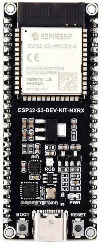
The ESP32-S3-DEV-KIT-2-N32R16V by Waveshare is a powerful microcontroller development board designed for IoT applications. It features dual-core processing, integrated Wi-Fi and Bluetooth capabilities, and a wide range of GPIO pins, making it ideal for projects requiring wireless communication, edge computing, or sensor integration. With its robust processing power and support for various peripherals, the ESP32-S3 is a versatile choice for both hobbyists and professionals.
Explore Projects Built with ESP32-S3
 Open Project in Cirkit Designer
 Open Project in Cirkit Designer
 Open Project in Cirkit Designer
 Open Project in Cirkit Designer
Explore Projects Built with ESP32-S3
Open Project in Cirkit DesignerOpen Project in Cirkit DesignerOpen Project in Cirkit DesignerOpen Project in Cirkit DesignerCommon Applications
- Smart home devices (e.g., smart lights, thermostats)
- IoT sensors and gateways
- Wearable devices
- Industrial automation
- Wireless data logging and monitoring
- Edge AI and machine learning applications
Technical Specifications
Key Technical Details
| Parameter | Value |
|---|---|
| Manufacturer | Waveshare |
| Part Number | ESP32-S3-DEV-KIT-2-N32R16V |
| Microcontroller | ESP32-S3 (dual-core Xtensa LX7 processor) |
| Clock Speed | Up to 240 MHz |
| Flash Memory | 16 MB |
| PSRAM | 8 MB |
| Wi-Fi | 802.11 b/g/n (2.4 GHz) |
| Bluetooth | Bluetooth 5.0 LE |
| GPIO Pins | 36 (multipurpose) |
| Operating Voltage | 3.3 V |
| Input Voltage Range | 5 V (via USB-C) |
| Communication Interfaces | UART, SPI, I2C, I2S, CAN, PWM |
| ADC Channels | 20 (12-bit resolution) |
| DAC Channels | 2 |
| USB Interface | USB-C (supports USB OTG) |
| Dimensions | 54 mm x 25 mm |
Pin Configuration and Descriptions
The ESP32-S3-DEV-KIT-2-N32R16V features a 2-row pin header layout. Below is a summary of the pin configuration:
| Pin Number | Pin Name | Functionality |
|---|---|---|
| 1 | 3V3 | 3.3V power output |
| 2 | GND | Ground |
| 3 | GPIO1 | General-purpose I/O, UART TX |
| 4 | GPIO2 | General-purpose I/O, UART RX |
| 5 | GPIO3 | General-purpose I/O, ADC, PWM |
| 6 | GPIO4 | General-purpose I/O, ADC, PWM |
| 7 | GPIO5 | General-purpose I/O, SPI MOSI |
| 8 | GPIO6 | General-purpose I/O, SPI MISO |
| 9 | GPIO7 | General-purpose I/O, SPI CLK |
| 10 | GPIO8 | General-purpose I/O, I2C SDA |
| 11 | GPIO9 | General-purpose I/O, I2C SCL |
| 12 | EN | Enable pin (active high) |
| 13 | BOOT | Boot mode selection |
| 14 | DAC1 | Digital-to-Analog Converter channel 1 |
| 15 | DAC2 | Digital-to-Analog Converter channel 2 |
Note: Refer to the official Waveshare datasheet for the complete pinout and advanced configurations.
Usage Instructions
How to Use the ESP32-S3 in a Circuit
Powering the Board:
- Use a USB-C cable to supply 5V to the board. The onboard voltage regulator will convert it to 3.3V for the microcontroller.
- Alternatively, you can power the board directly via the 3V3 pin.
Connecting Peripherals:
- Use the GPIO pins to connect sensors, actuators, or other peripherals. Ensure the voltage levels are compatible (3.3V logic).
- For communication, use the appropriate pins for UART, SPI, or I2C interfaces.
Programming the Board:
- Install the Arduino IDE or ESP-IDF (Espressif IoT Development Framework).
- Select the correct board (
ESP32-S3 Dev Module) and port in the IDE. - Write your code and upload it via the USB-C connection.
Flashing Firmware:
- Hold the BOOT button while pressing the EN button to enter firmware flashing mode.
- Use the Espressif Flash Tool or Arduino IDE to upload the firmware.
Important Considerations
- Voltage Levels: Ensure all connected peripherals operate at 3.3V logic levels to avoid damaging the board.
- Wi-Fi and Bluetooth Antenna: Avoid placing metallic objects near the onboard antenna to maintain signal strength.
- Heat Management: For intensive tasks, consider adding a heatsink to prevent overheating.
Example Code for Arduino IDE
The following example demonstrates how to blink an LED connected to GPIO5:
// Define the GPIO pin for the LED
#define LED_PIN 5

void setup() {
  // Set the LED pin as an output
  pinMode(LED_PIN, OUTPUT);
}

void loop() {
  // Turn the LED on
  digitalWrite(LED_PIN, HIGH);
  delay(1000); // Wait for 1 second

  // Turn the LED off
  digitalWrite(LED_PIN, LOW);
  delay(1000); // Wait for 1 second
}
Tip: Use the onboard LED (if available) by replacing
LED_PINwith the appropriate GPIO number.
Troubleshooting and FAQs
Common Issues and Solutions
Board Not Detected by Computer:
- Ensure the USB-C cable supports data transfer (not just charging).
- Check if the correct drivers for the ESP32-S3 are installed on your computer.
Wi-Fi Connection Fails:
- Verify the SSID and password in your code.
- Ensure the Wi-Fi network operates on the 2.4 GHz band (not 5 GHz).
Program Upload Fails:
- Hold the BOOT button while pressing the EN button to enter flashing mode.
- Check the selected COM port and board type in the Arduino IDE.
Peripheral Not Responding:
- Double-check the wiring and pin assignments in your code.
- Ensure the peripheral operates at 3.3V logic levels.
FAQs
Q: Can the ESP32-S3 run on battery power?
A: Yes, you can power the board using a 3.7V LiPo battery connected to the appropriate pins. Ensure the battery voltage is regulated to 3.3V.
Q: Does the ESP32-S3 support over-the-air (OTA) updates?
A: Yes, the ESP32-S3 supports OTA updates, allowing you to update firmware wirelessly.
Q: Can I use the ESP32-S3 for AI/ML applications?
A: Absolutely! The ESP32-S3 includes hardware acceleration for AI/ML tasks, making it suitable for edge computing applications.
For additional support, refer to the official Waveshare documentation or the Espressif community forums.