How to Use encoder: Examples, Pinouts, and Specs
Introduction
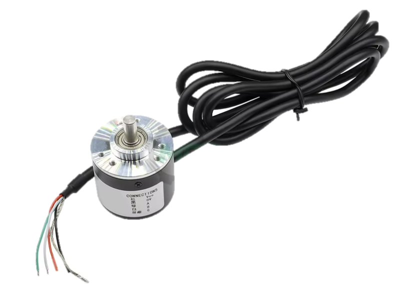
An encoder is an electronic device that converts motion, whether it's rotary or linear, into an electrical signal that can be read by a control system. This conversion allows for precise monitoring of position, speed, and direction. Encoders are widely used in robotics, industrial controls, automotive applications, and any system where precise motion control is required.
Explore Projects Built with encoder

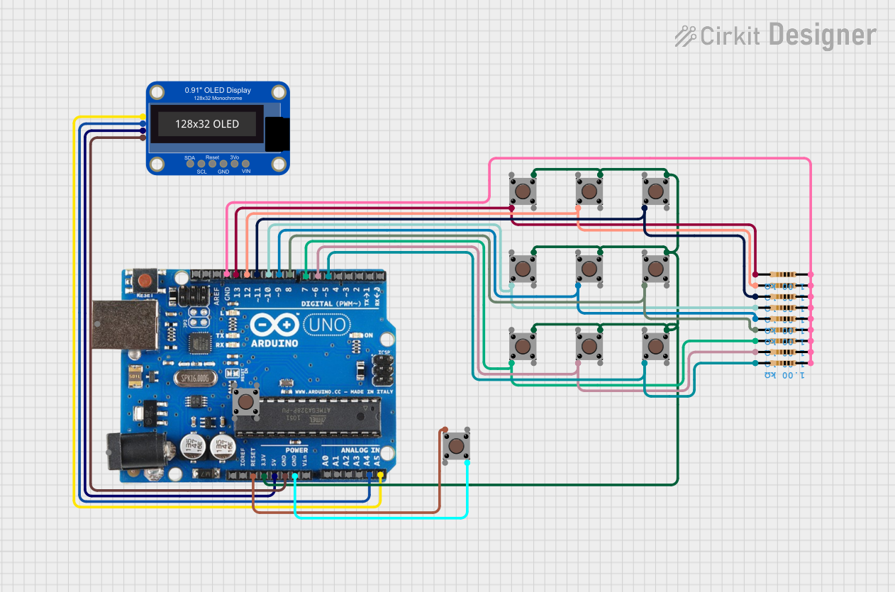
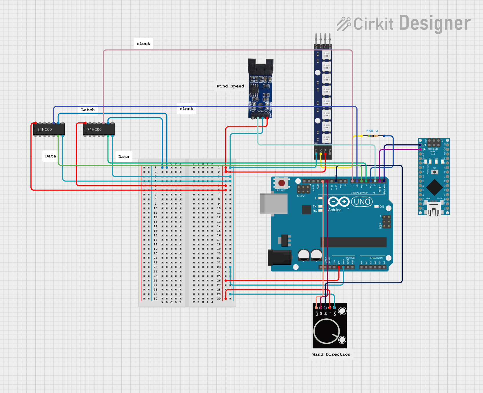

Explore Projects Built with encoder
Technical Specifications
Key Technical Details
- Resolution: Specifies the number of pulses per revolution (PPR) for rotary encoders or pulses per unit distance for linear encoders.
- Output Signal: Typically a square wave digital signal, but can also be analog.
- Supply Voltage: The required voltage for operation, often ranging from 3.3V to 24V.
- Maximum Rotational Speed: The highest speed at which the encoder can accurately read rotations.
- Operating Temperature: The range of temperatures within which the encoder can operate reliably.
Pin Configuration and Descriptions
| Pin Number | Name | Description |
|---|---|---|
| 1 | Vcc | Power supply input, typically 5V or 3.3V |
| 2 | GND | Ground connection |
| 3 | A | Output channel A, provides a square wave signal |
| 4 | B | Output channel B, provides a square wave signal 90° out of phase with channel A |
| 5 | Z | (Optional) Index pulse, provides a single pulse per revolution |
Usage Instructions
How to Use the Encoder in a Circuit
- Power Connection: Connect the Vcc pin to a power supply that matches the encoder's voltage rating, and connect the GND pin to the system ground.
- Signal Connection: Connect the output channels (A and B) to the digital input pins of a microcontroller or control system.
- Index Pulse (if available): Connect the Z pin to another digital input if you need to detect a specific position once per revolution.
Important Considerations and Best Practices
- Debouncing: Encoders are mechanical devices and may require debouncing either through hardware or software to ensure accurate readings.
- Pull-up Resistors: It's often necessary to use pull-up resistors on the output channels to ensure clean signal levels.
- Shielding: In electrically noisy environments, shielded cables can help prevent signal interference.
- Mounting: Proper mounting is crucial to ensure accurate readings and to avoid mechanical wear.
Example Code for Arduino UNO
// Define the encoder pins
const int encoderPinA = 2; // Channel A
const int encoderPinB = 3; // Channel B

// Variables to store encoder state
volatile int encoderPos = 0;
bool encoderALast = LOW;
bool encoderBLast = LOW;

void setup() {
  pinMode(encoderPinA, INPUT_PULLUP); // Set encoder pins as inputs
  pinMode(encoderPinB, INPUT_PULLUP);
  attachInterrupt(digitalPinToInterrupt(encoderPinA), readEncoder, CHANGE); // Interrupt on change
  Serial.begin(9600); // Start serial communication at 9600 baud
}

void loop() {
  // Main loop code here
}

// Interrupt service routine for reading the encoder
void readEncoder() {
  bool encoderA = digitalRead(encoderPinA);
  bool encoderB = digitalRead(encoderPinB);
  if (encoderA != encoderALast) { // If the A signal has changed
    if (encoderB != encoderA) { // If B is different from A, it's a CW rotation
      encoderPos++;
    } else { // If B is the same as A, it's a CCW rotation
      encoderPos--;
    }
  }
  encoderALast = encoderA; // Update the last state of A
  Serial.println(encoderPos); // Print the position
}
Troubleshooting and FAQs
Common Issues
- Jittery or Inconsistent Readings: This can be caused by electrical noise or mechanical bouncing. Implement debouncing and check for proper grounding and shielding.
- No Output Signal: Ensure that the encoder is properly powered and that the connections are secure. Also, verify that the encoder has not exceeded its maximum rotational speed or operating temperature range.
Solutions and Tips for Troubleshooting
- Debouncing: Implement software debouncing in the interrupt service routine or use hardware debouncing with capacitors and resistors.
- Check Connections: Loose connections can cause intermittent signals. Ensure all pins are securely connected.
- Test with a Multimeter: Use a multimeter to check for proper voltage levels at the power and output pins.
FAQs
Q: Can I use an encoder with a higher voltage rating on a 5V system? A: Yes, but ensure that the encoder's output signal levels are compatible with your system's logic levels.
Q: How do I determine the direction of rotation? A: By comparing the phase relationship of channels A and B, you can determine the direction of rotation. If A leads B, it's typically clockwise (CW); if B leads A, it's counterclockwise (CCW).
Q: What is the purpose of the Z channel? A: The Z channel provides a single pulse per revolution and can be used for precise position control or for finding a reference position.