How to Use Rotary Encoder with Knob: Examples, Pinouts, and Specs
Introduction
A Rotary Encoder with Knob is an electromechanical device that converts the angular position or motion of a shaft or axle to digital output signals. It is commonly used in applications that require precise control over parameters such as volume, position, or menu navigation in user interfaces. Unlike potentiometers, rotary encoders provide infinite rotation without a start or end point, making them ideal for applications where a full range of motion is necessary.
Explore Projects Built with Rotary Encoder with Knob

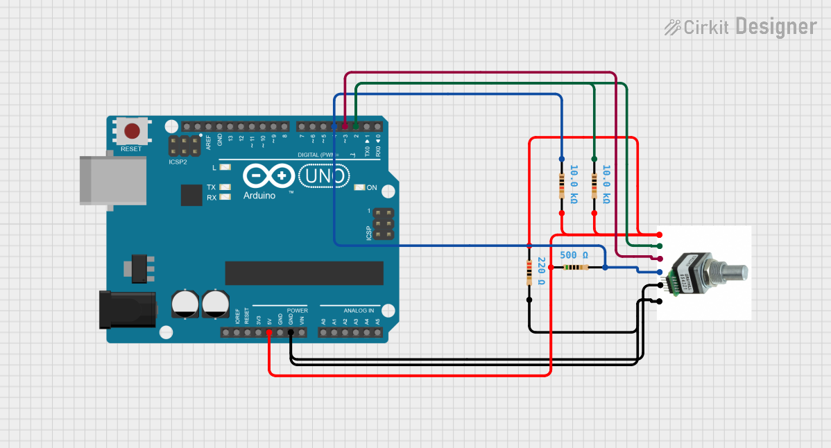
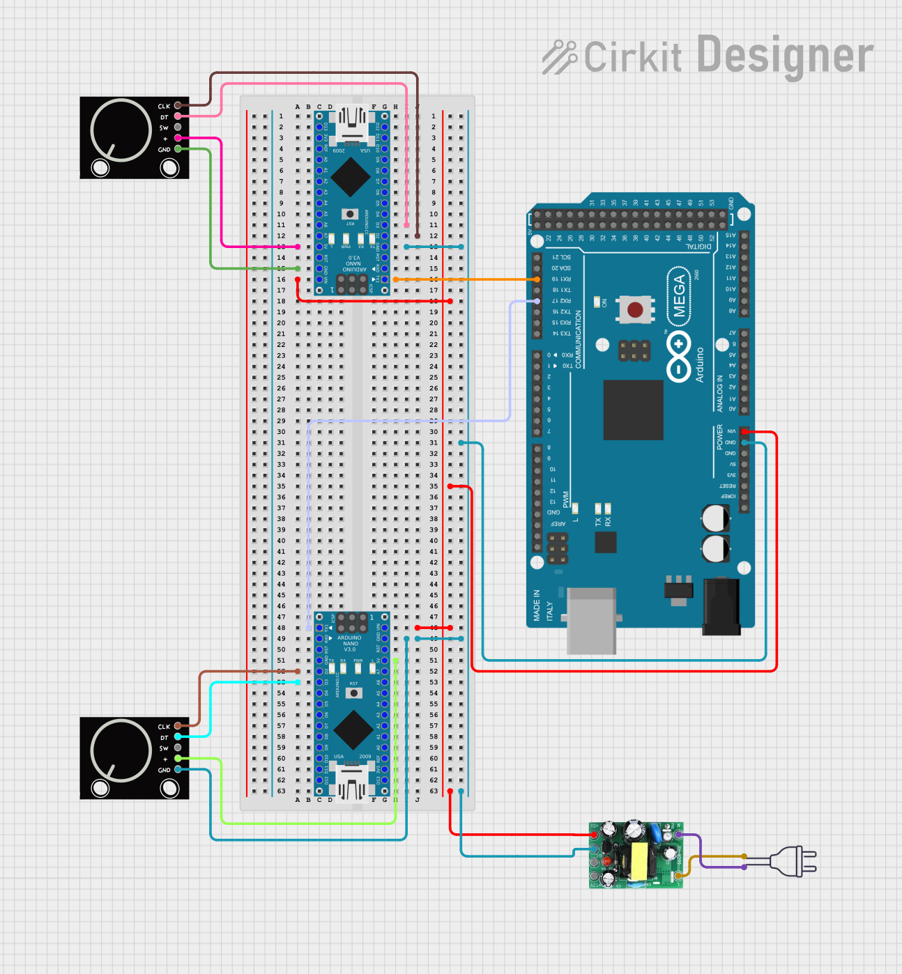
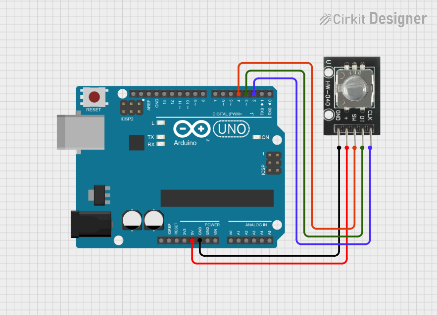
Explore Projects Built with Rotary Encoder with Knob
Technical Specifications
Key Technical Details
- Voltage Rating: Typically 3.3V to 5V
- Current Rating: Depends on the model, usually in the range of 10mA to 30mA
- Output Signal: Quadrature (incremental) digital signals
- Pulses per Revolution: Commonly 12 to 24, depending on the model
- Detents: Physical "clicks" per revolution, matching the pulses
- Shaft Type: Knurled or slotted for knob attachment
Pin Configuration and Descriptions
| Pin Number | Name | Description |
|---|---|---|
| 1 | GND | Ground connection |
| 2 | VCC | Power supply (3.3V to 5V) |
| 3 | SW | Pushbutton switch (active low) |
| 4 | DT | Data or B-phase output |
| 5 | CLK | Clock or A-phase output |
Usage Instructions
Connecting to a Circuit
- Connect the VCC pin to the positive supply voltage (3.3V or 5V).
- Connect the GND pin to the ground of the power supply.
- Connect the DT and CLK pins to two digital input pins on a microcontroller.
- Optionally, connect the SW pin to another digital input pin if the pushbutton feature is used.
Important Considerations and Best Practices
- Use pull-up resistors on the DT, CLK, and SW pins to ensure reliable signal levels.
- Debounce the rotary encoder signals either in hardware or software to prevent spurious readings.
- Monitor both the DT and CLK pins to determine the direction of rotation.
- Implement an interrupt service routine (ISR) for responsive and accurate reading of the encoder signals.
Example Code for Arduino UNO
// Define the connections to the Arduino
const int pinCLK = 2; // Connect to CLK on the rotary encoder
const int pinDT = 3;  // Connect to DT on the rotary encoder
const int pinSW = 4;  // Connect to SW on the rotary encoder

// Variables to hold the current and last encoder position
volatile int encoderPos = 0;
int lastEncoderPos = 0;

// Interrupt service routine for CLK
void isrCLK() {
  if (digitalRead(pinDT) != digitalRead(pinCLK)) {
    encoderPos++; // Clockwise
  } else {
    encoderPos--; // Counterclockwise
  }
}

// Interrupt service routine for SW
void isrSW() {
  // Implement switch functionality (e.g., reset position)
}

void setup() {
  pinMode(pinCLK, INPUT_PULLUP);
  pinMode(pinDT, INPUT_PULLUP);
  pinMode(pinSW, INPUT_PULLUP);

  // Attach the interrupt service routines
  attachInterrupt(digitalPinToInterrupt(pinCLK), isrCLK, CHANGE);
  attachInterrupt(digitalPinToInterrupt(pinSW), isrSW, FALLING);
}

void loop() {
  if (lastEncoderPos != encoderPos) {
    Serial.print("Position: ");
    Serial.println(encoderPos);
    lastEncoderPos = encoderPos;
  }
  // Additional code to handle the encoder position
}
Troubleshooting and FAQs
Common Issues
- Jittery or Inconsistent Readings: This is often due to a lack of debouncing. Implement software debouncing or use hardware debouncing circuits.
- No Response from Encoder: Ensure that the encoder is properly powered and that the pins are correctly connected. Check for any loose connections.
- Incorrect Direction Detection: Verify that the DT and CLK pins are connected to the correct pins on the microcontroller and that the ISR is correctly interpreting the signals.
Solutions and Tips for Troubleshooting
- Debouncing: Implement a simple software debounce by adding a delay or by checking for a stable state over several cycles.
- Testing Connections: Use a multimeter to check for continuity and correct voltages on the encoder pins.
- Code Debugging: Add serial print statements in the code to monitor the state of the encoder pins and the variables.
FAQs
Q: Can I use the rotary encoder without an external pull-up resistor? A: Yes, most microcontrollers, including the Arduino UNO, have internal pull-up resistors that can be enabled through software.
Q: How do I know if my rotary encoder is working? A: You can test the encoder by monitoring the output of the DT and CLK pins with an oscilloscope or by running a simple test code on a microcontroller to print the encoder position.
Q: What is the maximum rotation speed the encoder can handle? A: The maximum rotation speed depends on the specific model and the microcontroller's ability to read the signals. Refer to the datasheet for maximum mechanical speed and ensure your microcontroller's interrupt handling is fast enough.