Cirkit Designer Logo
Cirkit Designer
Your all-in-one circuit design IDE
Home / 
Component Documentation

How to Use Step-down 12 To 5V 5A XL4015: Examples, Pinouts, and Specs

Image of Step-down 12 To 5V 5A XL4015
Cirkit Designer LogoDesign with Step-down 12 To 5V 5A XL4015 in Cirkit Designer

Introduction

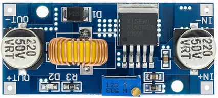
The XL4015 is a high-performance DC-DC buck converter designed to step down voltage from a higher input (e.g., 12V) to a lower output (e.g., 5V). It is capable of delivering a maximum output current of 5A, making it ideal for powering devices that require a stable 5V supply, such as microcontrollers, sensors, and USB-powered devices. The XL4015 is widely used in applications like battery charging, LED drivers, and power supply modules for embedded systems.

Explore Projects Built with Step-down 12 To 5V 5A XL4015

Use Cirkit Designer to design, explore, and prototype these projects online. Some projects support real-time simulation. Click "Open Project" to start designing instantly!
Battery-Powered DC Generator with XL4015 Buck Converter
Image of conveyor: A project utilizing Step-down 12 To 5V 5A XL4015 in a practical application
This circuit consists of a 12V battery connected to a rocker switch, which controls the input to an XL4015 DC Buck Step-down converter. The converter steps down the voltage to power a DC generator, with the generator's output connected back to the converter to form a feedback loop.
Cirkit Designer LogoOpen Project in Cirkit Designer
Dual Motor Control Circuit with Directional Switching and Voltage Regulation
Image of Pencuci Kipas: A project utilizing Step-down 12 To 5V 5A XL4015 in a practical application
This circuit features a 12V battery connected through a rocker switch to two buck converters, one of which steps down the voltage to power two DC mini metal gear motors, and the other is connected to a directional switch that controls a third DC mini metal gear motor. The XL4015 5A DC Buck Step-down converter's output is connected to two motors, allowing them to run at a reduced voltage, while the other buck converter's output is routed through a directional switch to control the direction of the third motor.
Cirkit Designer LogoOpen Project in Cirkit Designer
12V UPS System with Dual 18650 Li-ion Battery Backup and Voltage Regulation
Image of Power supply: A project utilizing Step-down 12 To 5V 5A XL4015 in a practical application
This circuit is designed to provide an uninterruptible power supply (UPS) system with a 12V DC output. It includes a 12V 5A power supply connected to an AC source through a toggle switch, which charges a pair of 18650 Li-ion batteries via a voltage regulator (XL4016). The UPS module ensures a continuous power supply to the load by switching between the power supply and the battery bank.
Cirkit Designer LogoOpen Project in Cirkit Designer
ESP32-Based Smart Energy Monitoring and Control System
Image of SMART SOCKET: A project utilizing Step-down 12 To 5V 5A XL4015 in a practical application
This circuit is designed to monitor AC voltage and current using ZMPT101B and ZMCT103C sensors, respectively, with an ESP32 microcontroller processing the sensor outputs. The XL4015 step-down module regulates the power supply to provide a stable voltage to the sensors, the ESP32, and an LCD I2C display. The ESP32 controls a 4-channel relay module for switching AC loads, and the system's operation can be interacted with via the LCD display and a push switch.
Cirkit Designer LogoOpen Project in Cirkit Designer

Explore Projects Built with Step-down 12 To 5V 5A XL4015

Use Cirkit Designer to design, explore, and prototype these projects online. Some projects support real-time simulation. Click "Open Project" to start designing instantly!
Image of conveyor: A project utilizing Step-down 12 To 5V 5A XL4015 in a practical application
Battery-Powered DC Generator with XL4015 Buck Converter
This circuit consists of a 12V battery connected to a rocker switch, which controls the input to an XL4015 DC Buck Step-down converter. The converter steps down the voltage to power a DC generator, with the generator's output connected back to the converter to form a feedback loop.
Cirkit Designer LogoOpen Project in Cirkit Designer
Image of Pencuci Kipas: A project utilizing Step-down 12 To 5V 5A XL4015 in a practical application
Dual Motor Control Circuit with Directional Switching and Voltage Regulation
This circuit features a 12V battery connected through a rocker switch to two buck converters, one of which steps down the voltage to power two DC mini metal gear motors, and the other is connected to a directional switch that controls a third DC mini metal gear motor. The XL4015 5A DC Buck Step-down converter's output is connected to two motors, allowing them to run at a reduced voltage, while the other buck converter's output is routed through a directional switch to control the direction of the third motor.
Cirkit Designer LogoOpen Project in Cirkit Designer
Image of Power supply: A project utilizing Step-down 12 To 5V 5A XL4015 in a practical application
12V UPS System with Dual 18650 Li-ion Battery Backup and Voltage Regulation
This circuit is designed to provide an uninterruptible power supply (UPS) system with a 12V DC output. It includes a 12V 5A power supply connected to an AC source through a toggle switch, which charges a pair of 18650 Li-ion batteries via a voltage regulator (XL4016). The UPS module ensures a continuous power supply to the load by switching between the power supply and the battery bank.
Cirkit Designer LogoOpen Project in Cirkit Designer
Image of SMART SOCKET: A project utilizing Step-down 12 To 5V 5A XL4015 in a practical application
ESP32-Based Smart Energy Monitoring and Control System
This circuit is designed to monitor AC voltage and current using ZMPT101B and ZMCT103C sensors, respectively, with an ESP32 microcontroller processing the sensor outputs. The XL4015 step-down module regulates the power supply to provide a stable voltage to the sensors, the ESP32, and an LCD I2C display. The ESP32 controls a 4-channel relay module for switching AC loads, and the system's operation can be interacted with via the LCD display and a push switch.
Cirkit Designer LogoOpen Project in Cirkit Designer

Technical Specifications

The XL4015 buck converter is designed for efficiency and reliability. Below are its key technical details:

General Specifications

Parameter Value
Input Voltage Range 4V to 38V
Output Voltage Range 1.25V to 36V (adjustable)
Maximum Output Current 5A
Output Power Up to 75W
Efficiency Up to 96%
Switching Frequency 180 kHz
Operating Temperature -40°C to +85°C
Dimensions 51mm x 26mm x 14mm

Pin Configuration and Descriptions

Pin Name Description
VIN Input voltage pin. Connect the positive terminal of the input power source.
GND Ground pin. Connect to the negative terminal of the input power source.
VOUT Output voltage pin. Provides the stepped-down voltage to the load.
ADJ Adjustment pin. Used to set the output voltage using a potentiometer.

Usage Instructions

How to Use the XL4015 in a Circuit

  1. Connect the Input Voltage:

    • Connect the positive terminal of the input power source (e.g., 12V) to the VIN pin.
    • Connect the negative terminal of the input power source to the GND pin.
  2. Set the Output Voltage:

    • Use the onboard potentiometer to adjust the output voltage.
    • Turn the potentiometer clockwise to increase the output voltage and counterclockwise to decrease it.
    • Use a multimeter to measure the output voltage at the VOUT pin to ensure it is set to 5V.
  3. Connect the Load:

    • Connect the positive terminal of the load to the VOUT pin.
    • Connect the negative terminal of the load to the GND pin.
  4. Power On:

    • Turn on the input power source. The XL4015 will step down the input voltage to the desired output voltage.

Important Considerations and Best Practices

  • Heat Dissipation: The XL4015 can generate heat during operation, especially at high currents. Ensure proper heat dissipation by attaching a heatsink or providing adequate airflow.
  • Input Voltage Range: Ensure the input voltage is within the specified range (4V to 38V) to avoid damaging the module.
  • Current Limitation: Do not exceed the maximum output current of 5A to prevent overheating or damage.
  • Output Voltage Adjustment: Always measure the output voltage with a multimeter after adjustment to ensure accuracy.
  • Polarity Protection: Double-check the polarity of the input and output connections to avoid damage to the module or connected devices.

Example: Using XL4015 with Arduino UNO

The XL4015 can be used to power an Arduino UNO by stepping down a 12V input to 5V. Below is an example circuit and code:

Circuit Connections

  • Connect a 12V DC power source to the VIN and GND pins of the XL4015.
  • Adjust the output voltage to 5V using the potentiometer.
  • Connect the VOUT pin of the XL4015 to the 5V pin of the Arduino UNO.
  • Connect the GND pin of the XL4015 to the GND pin of the Arduino UNO.

Example Code

// Example code to blink an LED connected to pin 13 of Arduino UNO
// Ensure the Arduino is powered by the XL4015 module (5V output).

void setup() {
  pinMode(13, OUTPUT); // Set pin 13 as an output pin
}

void loop() {
  digitalWrite(13, HIGH); // Turn the LED on
  delay(1000);            // Wait for 1 second
  digitalWrite(13, LOW);  // Turn the LED off
  delay(1000);            // Wait for 1 second
}

Troubleshooting and FAQs

Common Issues and Solutions

  1. No Output Voltage:

    • Cause: Incorrect input connections or insufficient input voltage.
    • Solution: Verify the input voltage is within the specified range and check the polarity of the connections.
  2. Overheating:

    • Cause: Excessive current draw or inadequate heat dissipation.
    • Solution: Ensure the load does not exceed 5A and attach a heatsink to the module.
  3. Output Voltage Not Stable:

    • Cause: Poor input power quality or incorrect adjustment of the potentiometer.
    • Solution: Use a stable DC power source and carefully adjust the potentiometer while monitoring the output voltage.
  4. Output Voltage Too High or Low:

    • Cause: Potentiometer not set correctly.
    • Solution: Re-adjust the potentiometer and measure the output voltage with a multimeter.

FAQs

  • Q: Can the XL4015 be used to charge batteries?
    A: Yes, the XL4015 can be used for battery charging applications. However, ensure the output voltage and current are set according to the battery's specifications.

  • Q: Is the XL4015 protected against reverse polarity?
    A: No, the XL4015 does not have built-in reverse polarity protection. Always double-check the polarity of your connections.

  • Q: Can I use the XL4015 to power a Raspberry Pi?
    A: Yes, the XL4015 can step down 12V to 5V to power a Raspberry Pi. Ensure the output voltage is precisely set to 5V and the current requirement of the Raspberry Pi is met.

  • Q: How do I know if the module is overheating?
    A: If the module becomes too hot to touch or the output voltage becomes unstable, it may be overheating. Use a heatsink or reduce the load to prevent damage.