Cirkit Designer
Your all-in-one circuit design IDE
Home /
Component Documentation
How to Use RELAY MODULE: Examples, Pinouts, and Specs
Introduction
A relay module is an electronic device that acts as a switch, which can be controlled by an external circuit. It allows a low-power signal to control a much higher power circuit. Relay modules are commonly used in applications where it is necessary to control a high power or high voltage load with a low voltage, such as home appliances, industrial machines, and automation systems.
Explore Projects Built with RELAY MODULE
DC-DC Converter and Relay Module Power Distribution System

This circuit consists of a DC-DC converter powering a 6-channel power module, which in turn supplies 5V to a 2-relay module. The power module distributes the converted voltage to the relay module, enabling it to control external devices.
ESP32-Powered 8-Channel Relay Controller with Wi-Fi Connectivity

This circuit features an ESP32 microcontroller connected to an 8-channel relay module. The ESP32 controls the relay channels via its GPIO pins, allowing for the switching of external devices or loads through the relays.
ESP32-Powered Wi-Fi Controlled 8-Channel Relay Module

This circuit features an ESP32 microcontroller connected to an 8-channel relay module. The ESP32 controls the relay channels via its GPIO pins, allowing it to switch multiple external devices on and off. The ESP32 also provides power to the relay module.
ESP32-Controlled LoRa and Dual Relay System
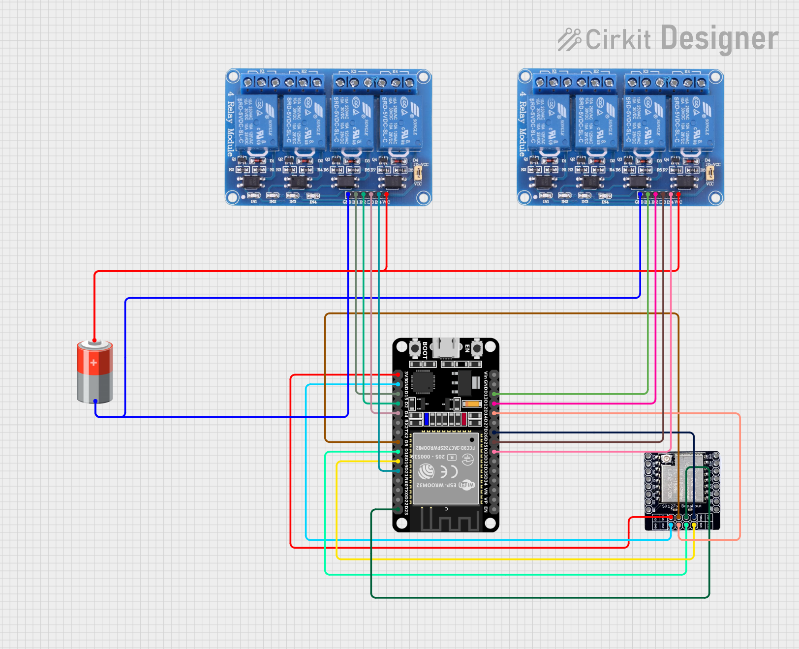
This circuit features an ESP32 microcontroller connected to two 4-channel relay modules and a LORA_RA02 module. The ESP32 uses its GPIO pins to control the relay channels, enabling switching of connected devices, and to communicate with the LORA_RA02 module for wireless data transmission. The relays and the LORA module are powered by a 5v battery, with common ground shared across the components.
Explore Projects Built with RELAY MODULE
DC-DC Converter and Relay Module Power Distribution System
This circuit consists of a DC-DC converter powering a 6-channel power module, which in turn supplies 5V to a 2-relay module. The power module distributes the converted voltage to the relay module, enabling it to control external devices.
ESP32-Powered 8-Channel Relay Controller with Wi-Fi Connectivity
This circuit features an ESP32 microcontroller connected to an 8-channel relay module. The ESP32 controls the relay channels via its GPIO pins, allowing for the switching of external devices or loads through the relays.
ESP32-Powered Wi-Fi Controlled 8-Channel Relay Module
This circuit features an ESP32 microcontroller connected to an 8-channel relay module. The ESP32 controls the relay channels via its GPIO pins, allowing it to switch multiple external devices on and off. The ESP32 also provides power to the relay module.
ESP32-Controlled LoRa and Dual Relay System
This circuit features an ESP32 microcontroller connected to two 4-channel relay modules and a LORA_RA02 module. The ESP32 uses its GPIO pins to control the relay channels, enabling switching of connected devices, and to communicate with the LORA_RA02 module for wireless data transmission. The relays and the LORA module are powered by a 5v battery, with common ground shared across the components.
Common Applications and Use Cases
- Home automation (e.g., turning lights on/off)
- Controlling motors, fans, and pumps
- Switching power to high voltage/current devices
- Interfacing microcontrollers with high-power circuits
Technical Specifications
Key Technical Details
- Operating Voltage: Typically 5V, 12V, or 24V DC
- Switching Voltage: Up to 250V AC or 30V DC
- Current Rating: Often 10A for AC loads or 7A for DC loads
- Contact Type: Normally Open (NO), Normally Closed (NC), Common (COM)
Pin Configuration and Descriptions
| Pin Name | Description |
|---|---|
| VCC | Connects to the power supply voltage (e.g., 5V) |
| GND | Connects to the ground of the power supply |
| IN | Input signal that activates the relay (active LOW or HIGH depending on the module) |
| NO | Normally Open contact, closes when relay is activated |
| NC | Normally Closed contact, opens when relay is activated |
| COM | Common contact, connects to NO or NC |
Usage Instructions
How to Use the Relay Module in a Circuit
- Connect the VCC pin to the positive terminal of your power supply.
- Connect the GND pin to the ground terminal of your power supply.
- Connect the IN pin to a digital output pin of a microcontroller, such as an Arduino.
- Connect your load to the NO or NC and COM terminals, depending on whether you want the load to be powered when the relay is activated or not.
Important Considerations and Best Practices
- Ensure the power ratings of the relay match the requirements of your load.
- Use a diode across the relay coil to prevent back EMF when the relay deactivates.
- Consider using a transistor to drive the relay if the control signal is not sufficient.
- Always ensure proper isolation between the low voltage and high voltage sides.
Example Code for Arduino UNO
// Define the relay control pin
const int relayPin = 2;

void setup() {
  // Set the relay pin as an output
  pinMode(relayPin, OUTPUT);
}

void loop() {
  // Turn on the relay (assuming active LOW)
  digitalWrite(relayPin, LOW);
  delay(1000); // Wait for 1 second

  // Turn off the relay
  digitalWrite(relayPin, HIGH);
  delay(1000); // Wait for 1 second
}
Troubleshooting and FAQs
Common Issues Users Might Face
- Relay does not activate: Check the input signal and power supply connections.
- Intermittent operation: Verify that the relay's current and voltage ratings are not exceeded.
- Noise issues: Use snubber circuits or opto-isolators to mitigate electrical noise.
Solutions and Tips for Troubleshooting
- Ensure all connections are secure and free from corrosion.
- If using a microcontroller, verify that the code is uploaded correctly and that the correct pin is being used.
- Use a multimeter to check the continuity of the relay contacts when activated.
FAQs
Q: Can I control a relay module directly with an Arduino?
- A: Yes, most relay modules can be controlled directly with an Arduino's digital output pins.
Q: What is the purpose of the NC contact?
- A: The NC (Normally Closed) contact allows the relay to pass current when not activated, which can be useful for fail-safe applications.
Q: How can I control multiple relay modules with an Arduino?
- A: You can control multiple relays by connecting each relay's input pin to a separate digital output pin on the Arduino and controlling them individually in your code.
Remember to always follow safety guidelines when working with high voltage and current.