How to Use Adafruit Radio FeatherWing: Examples, Pinouts, and Specs
Introduction
The Adafruit Radio FeatherWing is an add-on module that endows Feather boards with wireless communication functionalities. It is designed to be compatible with a range of radio protocols such as LoRa (Long Range), RFM69, and RFM9X, making it a versatile choice for projects that require remote communication. Common applications include remote sensors, home automation, and IoT devices where long-range or low-power data transmission is essential.
Explore Projects Built with Adafruit Radio FeatherWing

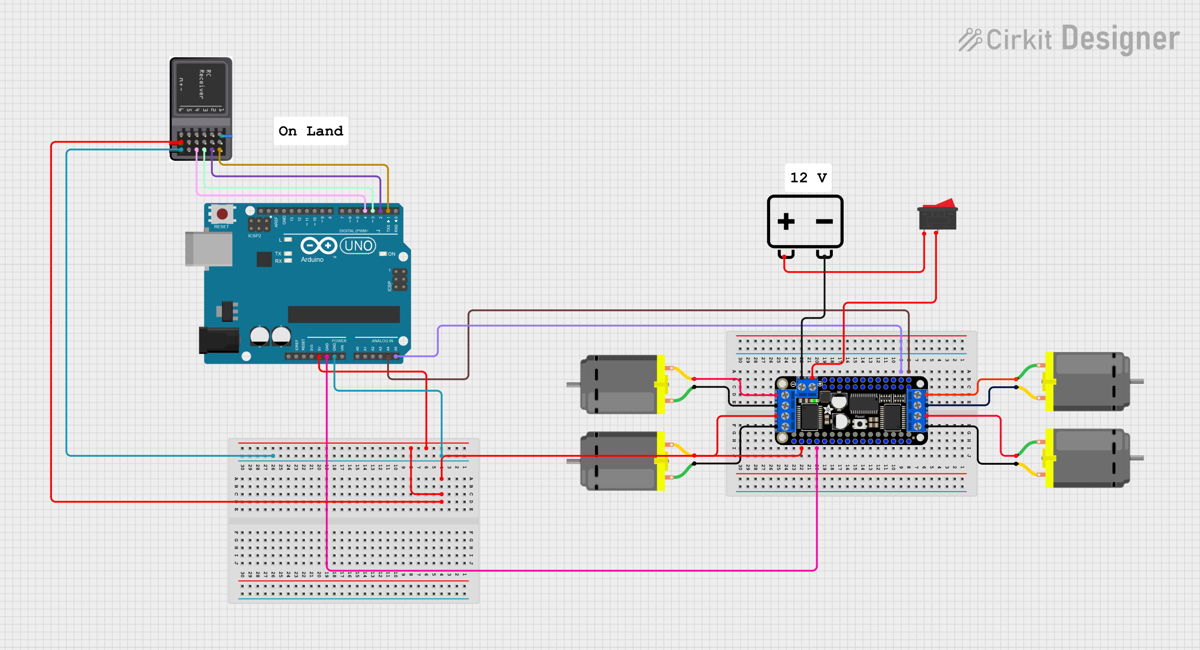
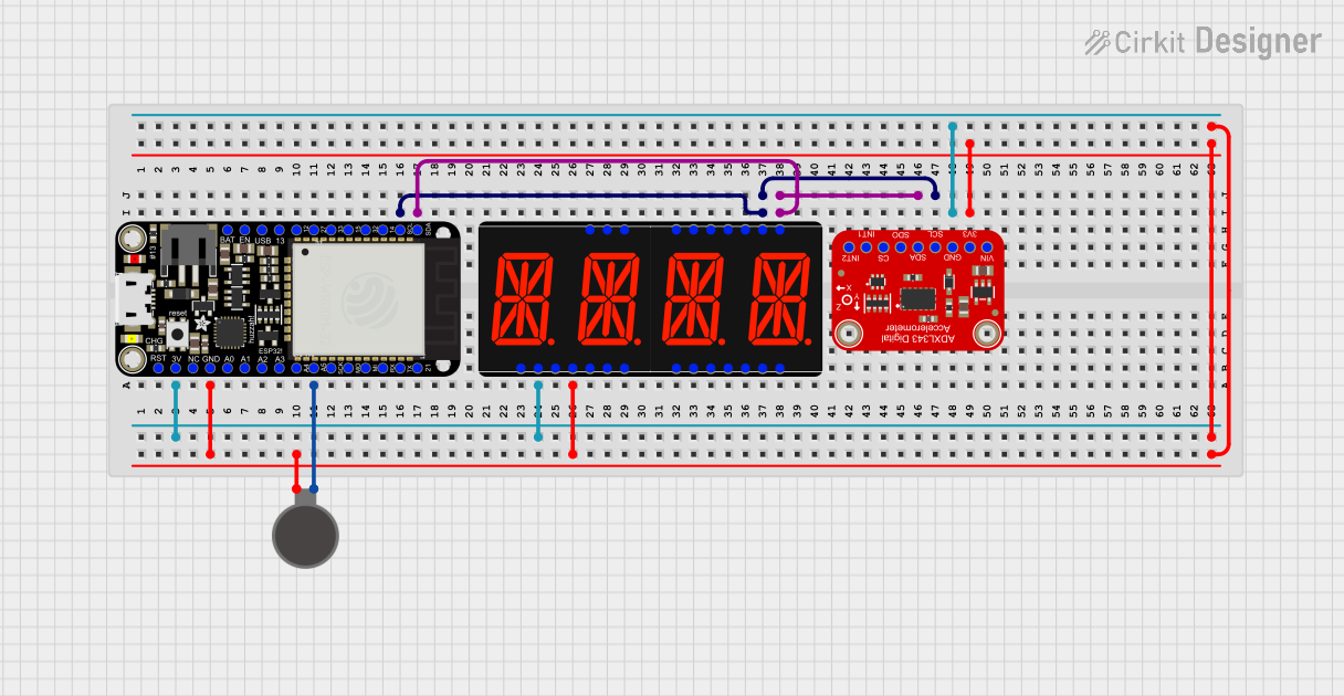
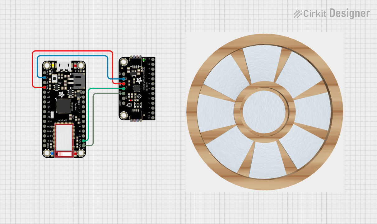
Explore Projects Built with Adafruit Radio FeatherWing
Technical Specifications
Key Technical Details
- Operating Voltage: 3.3V (Do not exceed 3.3V as it may damage the module)
- Frequency Bands: Depending on the model, 433MHz, 868MHz, or 915MHz
- Output Power: Up to +20 dBm
- Sensitivity: Down to -120 dBm at 1.2 kbps
- Modulation Types: FSK, GFSK, MSK, GMSK, LoRaTM, OOK
- Interface: SPI
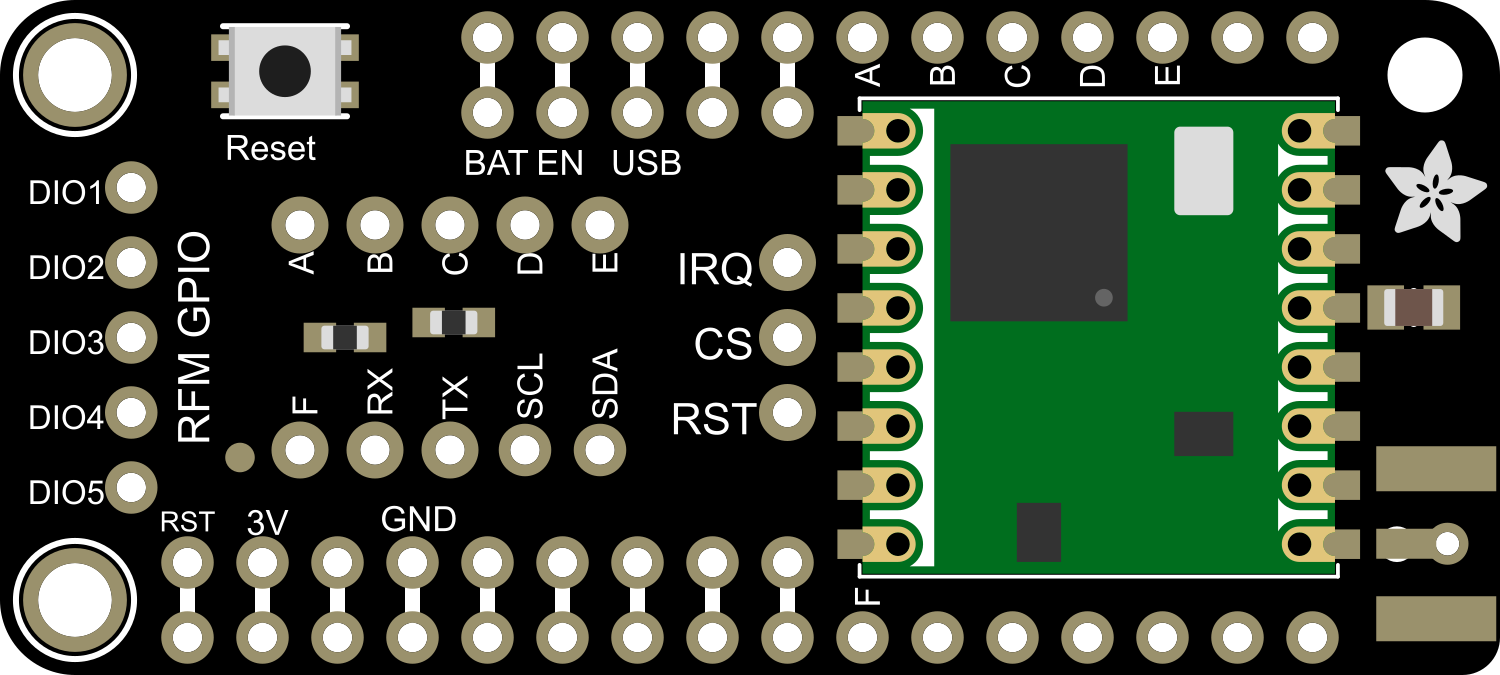
Pin Configuration and Descriptions
| Pin Number | Name | Description |
|---|---|---|
| 1 | GND | Ground connection |
| 2 | 3V | 3.3V power supply input |
| 3 | SCK | SPI Clock |
| 4 | MISO | SPI Master In Slave Out |
| 5 | MOSI | SPI Master Out Slave In |
| 6 | CS | SPI Chip Select |
| 7 | RST | Reset pin |
| 8 | G0 | Interrupt/GPIO0 |
| 9 | G1 | GPIO1 (optional use) |
| 10 | G2 | GPIO2 (optional use) |
Usage Instructions
Integration with Feather Boards
To use the Adafruit Radio FeatherWing with a Feather board:
- Align the headers of the Radio FeatherWing with the corresponding sockets on the Feather board.
- Solder the headers to establish a secure and reliable connection.
- Ensure that the antenna is properly connected to the module before powering it up to avoid damage to the radio circuitry.
Programming and Best Practices
- Use the Adafruit-provided libraries for interfacing with the module.
- Always perform range testing in the actual environment where the system will be deployed.
- Ensure that the chosen frequency band complies with local regulations.
- When designing the enclosure, consider the antenna placement for optimal signal strength.
Example Code for Arduino UNO
Below is an example code snippet for initializing the Adafruit Radio FeatherWing with an Arduino UNO. This example assumes the use of the LoRa protocol.
#include <SPI.h>
#include <RH_RF95.h>

// Singleton instance of the radio driver
RH_RF95 rf95;

void setup() {
  Serial.begin(9600);
  while (!Serial) {
    ; // Wait for serial port to be available
  }

  if (!rf95.init()) {
    Serial.println("LoRa radio init failed");
    while (1);
  }
  Serial.println("LoRa radio init OK!");

  // Set frequency
  if (!rf95.setFrequency(915.0)) {
    Serial.println("setFrequency failed");
    while (1);
  }

  // Optionally set the transmitter power. Here we use the maximum.
  rf95.setTxPower(23, false);
}

void loop() {
  // Your code to send and receive messages goes here
}
Remember to install the RadioHead library which is required for this code to work. You can install it through the Arduino Library Manager or download it from the RadioHead project page.
Troubleshooting and FAQs
Common Issues
- No communication between modules: Ensure that both modules are on the same frequency and using the same settings.
- Short range: Check the antenna connections and orientation. Also, verify that there are no obstructions or interference sources.
- Module not responding: Make sure the module is correctly powered and that the SPI connections are secure.
Solutions and Tips
- Antenna Type: Using a higher gain antenna can improve range but ensure it is suitable for the frequency band.
- Power Supply: A stable and clean power supply is crucial for the module's performance.
- Interference: Keep the module away from devices that can cause RF interference.
FAQs
Q: Can I use the Adafruit Radio FeatherWing with other microcontrollers?
A: Yes, as long as the microcontroller supports SPI communication and operates at 3.3V logic levels.
Q: What is the maximum range I can achieve with the Radio FeatherWing?
A: The range depends on many factors, including the environment, antenna type, and settings. LoRa can achieve several kilometers under ideal conditions.
Q: Is it necessary to use an external antenna?
A: Yes, an external antenna is required for the module to transmit and receive signals effectively.
For further assistance, consult the Adafruit forums or the product's official page for community support and additional resources.