How to Use GPS atgm336H: Examples, Pinouts, and Specs
Introduction
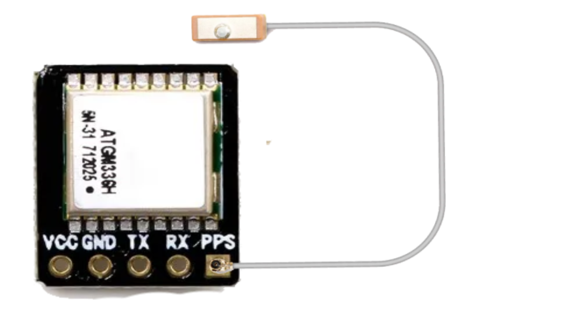
The ATGM336H is a high-performance GPS receiver module designed to deliver accurate and reliable positioning data. It features a built-in antenna, low power consumption, and a compact design, making it ideal for integration into a wide range of applications. This module supports multiple satellite navigation systems, including GPS, GLONASS, and BeiDou, ensuring robust performance in diverse environments.
Explore Projects Built with GPS atgm336H

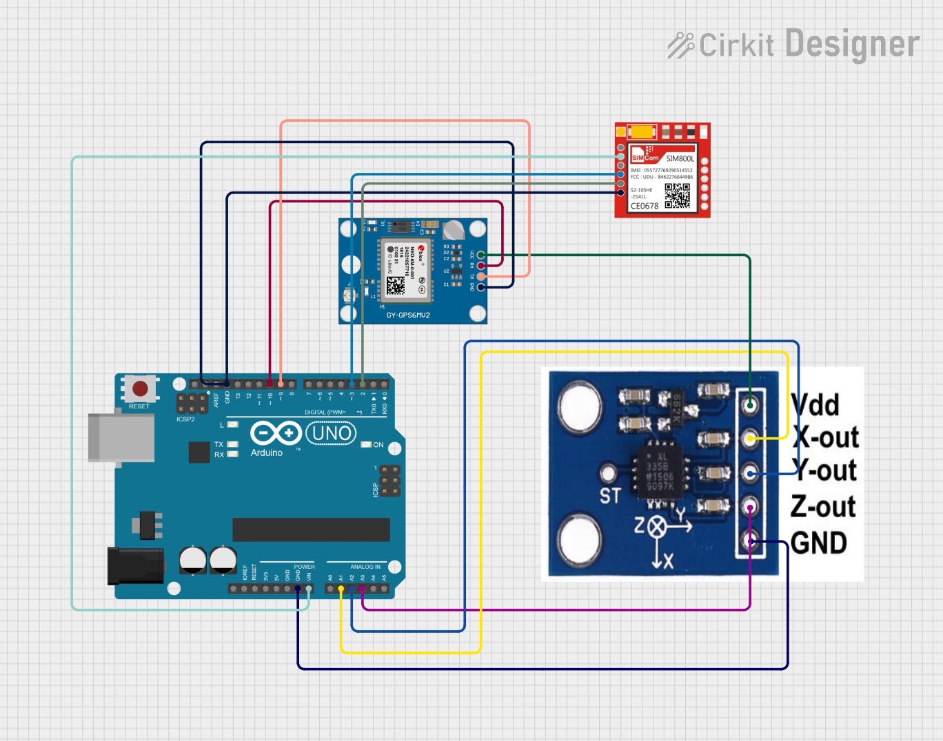
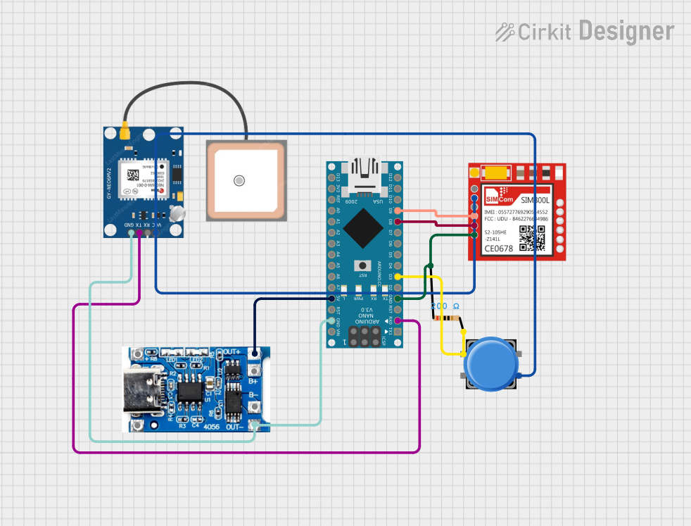

Explore Projects Built with GPS atgm336H
Common Applications and Use Cases
- Automotive navigation systems
- Robotics and autonomous vehicles
- Internet of Things (IoT) devices
- Asset tracking and fleet management
- Outdoor sports and fitness devices
- Geographic surveying and mapping
Technical Specifications
The ATGM336H module is engineered for precision and efficiency. Below are its key technical details:
Key Technical Details
| Parameter | Specification |
|---|---|
| Satellite Systems | GPS, GLONASS, BeiDou |
| Positioning Accuracy | 2.5 meters CEP (Circular Error Probable) |
| Cold Start Time | < 35 seconds |
| Hot Start Time | < 1 second |
| Update Rate | 1 Hz (default), configurable up to 10 Hz |
| Operating Voltage | 3.0V to 5.0V |
| Power Consumption | < 30 mA @ 3.3V |
| Communication Interface | UART (default baud rate: 9600 bps) |
| Operating Temperature | -40°C to +85°C |
| Dimensions | 16 mm x 12.2 mm x 2.4 mm |
Pin Configuration and Descriptions
The ATGM336H module has a simple pinout for easy integration. Below is the pin configuration:
| Pin Number | Pin Name | Description |
|---|---|---|
| 1 | VCC | Power supply input (3.0V to 5.0V) |
| 2 | GND | Ground connection |
| 3 | TXD | UART Transmit Data (GPS data output) |
| 4 | RXD | UART Receive Data (for configuration commands) |
| 5 | PPS | Pulse Per Second output (timing synchronization) |
| 6 | NC | Not connected (leave unconnected) |
Usage Instructions
The ATGM336H module is straightforward to use in a circuit. Follow the steps below to integrate it into your project:
Connecting the ATGM336H
- Power Supply: Connect the
VCCpin to a 3.3V or 5V power source and theGNDpin to ground. - UART Communication: Connect the
TXDpin to the RX pin of your microcontroller and theRXDpin to the TX pin of your microcontroller. - PPS Signal (Optional): If precise timing is required, connect the
PPSpin to a GPIO pin on your microcontroller.
Important Considerations
- Ensure the module has a clear view of the sky for optimal satellite reception.
- Avoid placing the module near sources of electromagnetic interference (e.g., motors, high-frequency circuits).
- Use a decoupling capacitor (e.g., 10 µF) between
VCCandGNDto stabilize the power supply.
Example: Using the ATGM336H with Arduino UNO
Below is an example of how to interface the ATGM336H with an Arduino UNO to read GPS data:
Circuit Connections
- Connect
VCCto the 5V pin on the Arduino. - Connect
GNDto the GND pin on the Arduino. - Connect
TXDon the ATGM336H to pin 4 (software RX) on the Arduino. - Connect
RXDon the ATGM336H to pin 3 (software TX) on the Arduino.
Arduino Code
#include <SoftwareSerial.h>

// Define software serial pins for GPS communication
SoftwareSerial gpsSerial(4, 3); // RX = pin 4, TX = pin 3

void setup() {
  Serial.begin(9600);          // Initialize serial monitor
  gpsSerial.begin(9600);       // Initialize GPS module communication
  Serial.println("GPS Module Initialized");
}

void loop() {
  // Check if data is available from the GPS module
  while (gpsSerial.available()) {
    char c = gpsSerial.read(); // Read one character from GPS
    Serial.print(c);           // Print the character to the serial monitor
  }
}
Notes
- The default baud rate of the ATGM336H is 9600 bps. If you need to change it, use configuration commands via the
RXDpin. - Use a GPS parsing library (e.g., TinyGPS++) for easier handling of NMEA sentences.
Troubleshooting and FAQs
Common Issues and Solutions
No GPS Data Output
- Cause: The module may not have a clear view of the sky.
- Solution: Move the module to an open area with minimal obstructions.
Incorrect or Inconsistent Positioning
- Cause: Insufficient satellite signals or interference.
- Solution: Ensure the module is away from sources of interference and has a stable power supply.
Module Not Responding
- Cause: Incorrect wiring or baud rate mismatch.
- Solution: Double-check the connections and ensure the baud rate is set to 9600 bps.
PPS Signal Not Detected
- Cause: PPS pin not connected or timing not configured.
- Solution: Verify the connection to the PPS pin and consult the module's datasheet for timing configuration.
FAQs
Q: Can the ATGM336H work indoors?
A: The module is designed for outdoor use and requires a clear view of the sky for optimal performance. It may work indoors near windows but with reduced accuracy.
Q: How many satellites does the ATGM336H support?
A: The module can track up to 22 satellites simultaneously, depending on the satellite system in use.
Q: Can I increase the update rate beyond 1 Hz?
A: Yes, the update rate is configurable up to 10 Hz using specific configuration commands via the UART interface.
Q: Is an external antenna required?
A: No, the ATGM336H has a built-in antenna. However, an external antenna can be used for improved performance in challenging environments.
By following this documentation, you can effectively integrate and utilize the ATGM336H GPS module in your projects.