How to Use LDR: Examples, Pinouts, and Specs
Introduction
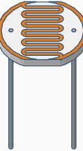
A Light Dependent Resistor (LDR), also known as a photoresistor, is a passive electronic component whose resistance decreases as the intensity of incident light increases. This property makes it an ideal choice for light sensing and control applications. LDRs are widely used in devices such as automatic streetlights, light meters, and alarm systems.
Explore Projects Built with LDR
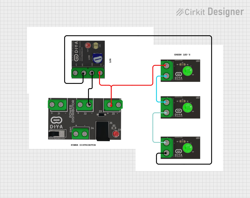
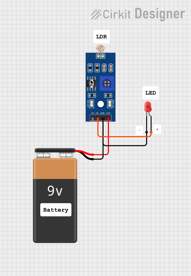
Explore Projects Built with LDR
Common Applications and Use Cases
- Automatic lighting systems (e.g., streetlights that turn on at dusk)
- Light intensity measurement devices
- Solar tracking systems
- Alarm systems triggered by changes in light
- Electronic toys and consumer electronics
Technical Specifications
Below are the general technical specifications of a typical LDR. Note that exact values may vary depending on the specific model or manufacturer.
| Parameter | Value |
|---|---|
| Resistance (Dark) | 1 MΩ to 10 MΩ (typical) |
| Resistance (Bright Light) | 1 kΩ to 10 kΩ (typical) |
| Maximum Voltage | 150 V |
| Power Dissipation | 100 mW |
| Spectral Response | 400 nm to 700 nm (visible light) |
| Response Time (Rise) | 20 ms to 30 ms |
| Response Time (Fall) | 30 ms to 50 ms |
| Operating Temperature | -30°C to +70°C |
Pin Configuration and Descriptions
An LDR is a two-terminal device with no polarity. The terminals are interchangeable, and the component can be connected in either direction in a circuit.
| Pin | Description |
|---|---|
| Pin 1 | One terminal of the LDR |
| Pin 2 | The other terminal of the LDR |
Usage Instructions
How to Use the LDR in a Circuit
Basic Circuit Connection:
- Connect one terminal of the LDR to a voltage source (e.g., 5V).
- Connect the other terminal to a resistor (typically 10 kΩ) in series, and then to ground.
- The junction between the LDR and the resistor serves as the output voltage point, which varies with light intensity.
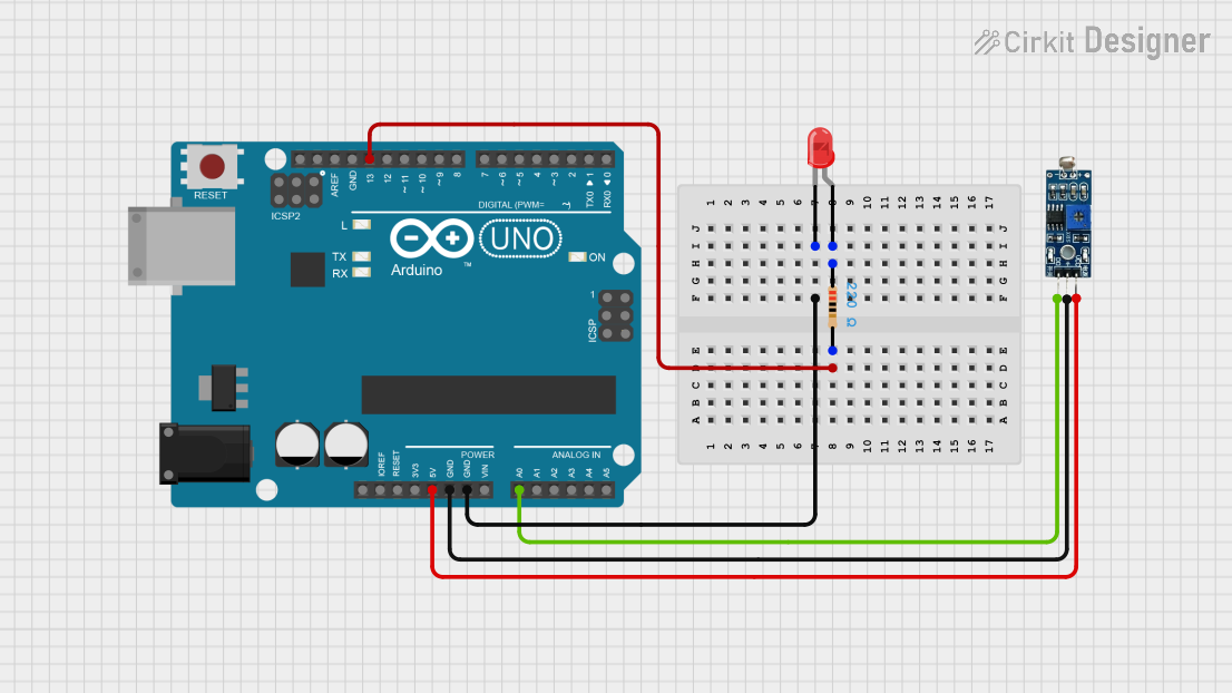
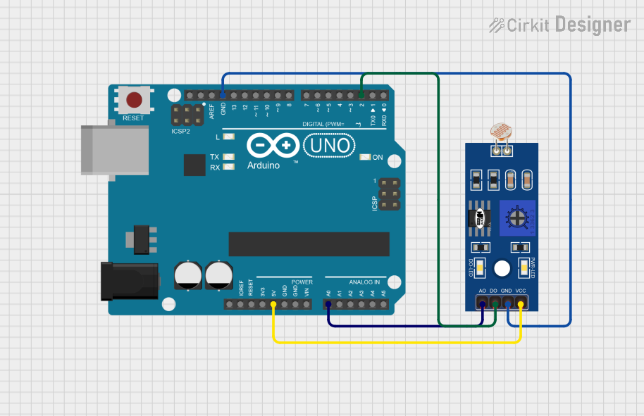
Interfacing with a Microcontroller (e.g., Arduino UNO):
- Connect the LDR-resistor junction to an analog input pin of the Arduino.
- Use the Arduino's ADC (Analog-to-Digital Converter) to read the voltage and determine the light intensity.
Important Considerations:
- Use a pull-down resistor to ensure stable readings.
- Avoid exposing the LDR to extreme temperatures or high-intensity light for prolonged periods, as this may degrade its performance.
- Shield the LDR from electrical noise in sensitive applications.
Sample Arduino Code
Below is an example of how to use an LDR with an Arduino UNO to measure light intensity and display the readings in the Serial Monitor.
// Define the analog pin connected to the LDR
const int ldrPin = A0; // LDR connected to analog pin A0

void setup() {
  Serial.begin(9600); // Initialize serial communication at 9600 baud
}

void loop() {
  int ldrValue = analogRead(ldrPin); // Read the analog value from the LDR
  float voltage = ldrValue * (5.0 / 1023.0); // Convert ADC value to voltage

  // Print the LDR value and voltage to the Serial Monitor
  Serial.print("LDR Value: ");
  Serial.print(ldrValue);
  Serial.print(" | Voltage: ");
  Serial.println(voltage);

  delay(500); // Wait for 500 ms before the next reading
}
Best Practices
- Use a potentiometer in place of the fixed resistor for adjustable sensitivity.
- Place the LDR in a location where it can accurately sense the desired light source.
- If used outdoors, protect the LDR with a transparent cover to shield it from dust and moisture.
Troubleshooting and FAQs
Common Issues and Solutions
Inconsistent Readings:
- Cause: Electrical noise or unstable connections.
- Solution: Use a capacitor (e.g., 0.1 µF) across the LDR terminals to filter noise. Ensure all connections are secure.
No Response to Light Changes:
- Cause: Incorrect wiring or damaged LDR.
- Solution: Verify the circuit connections and replace the LDR if necessary.
Low Sensitivity:
- Cause: Improper resistor value in the voltage divider.
- Solution: Adjust the resistor value to optimize sensitivity for the specific light conditions.
Overheating:
- Cause: Exceeding the maximum voltage or power rating.
- Solution: Ensure the voltage and power dissipation are within the specified limits.
FAQs
Q1: Can an LDR detect infrared light?
A1: No, LDRs are designed to respond to visible light (400 nm to 700 nm). For infrared detection, use a photodiode or phototransistor.
Q2: How do I choose the resistor value for the voltage divider?
A2: The resistor value should be comparable to the LDR's resistance under typical lighting conditions. For example, use a 10 kΩ resistor if the LDR's resistance is around 10 kΩ in ambient light.
Q3: Can I use an LDR in a digital circuit?
A3: Yes, but you will need to use an analog-to-digital converter (ADC) or a comparator circuit to process the LDR's analog output.
Q4: Is the LDR polarity-sensitive?
A4: No, the LDR is not polarity-sensitive and can be connected in either direction.