
How to Use NodeMCU 32 38 Pin: Examples, Pinouts, and Specs
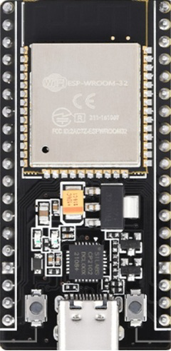
 Design with NodeMCU 32 38 Pin in Cirkit Designer
Introduction
The NodeMCU 32 38 Pin, manufactured by NodeMCU with part ID ESP 32S, is a low-cost, open-source IoT platform based on the ESP32 chip. It features dual-mode Wi-Fi and Bluetooth capabilities, making it ideal for a wide range of wireless communication applications. Designed for easy integration with various sensors and actuators, this module is widely used in IoT projects, home automation, and wireless data transmission systems.
Explore Projects Built with NodeMCU 32 38 Pin
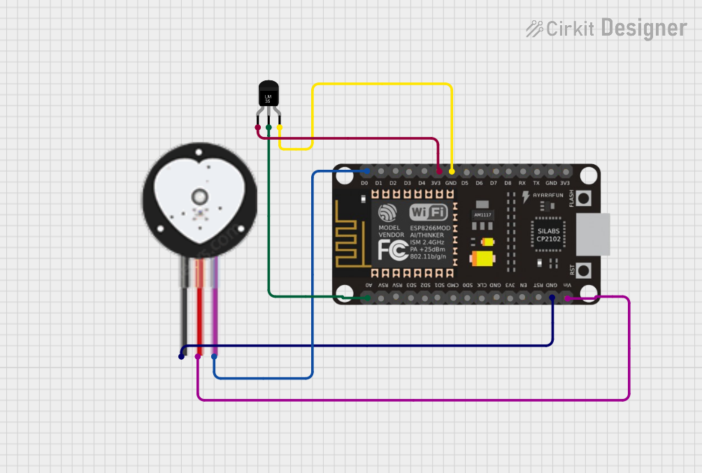 Open Project in Cirkit Designer
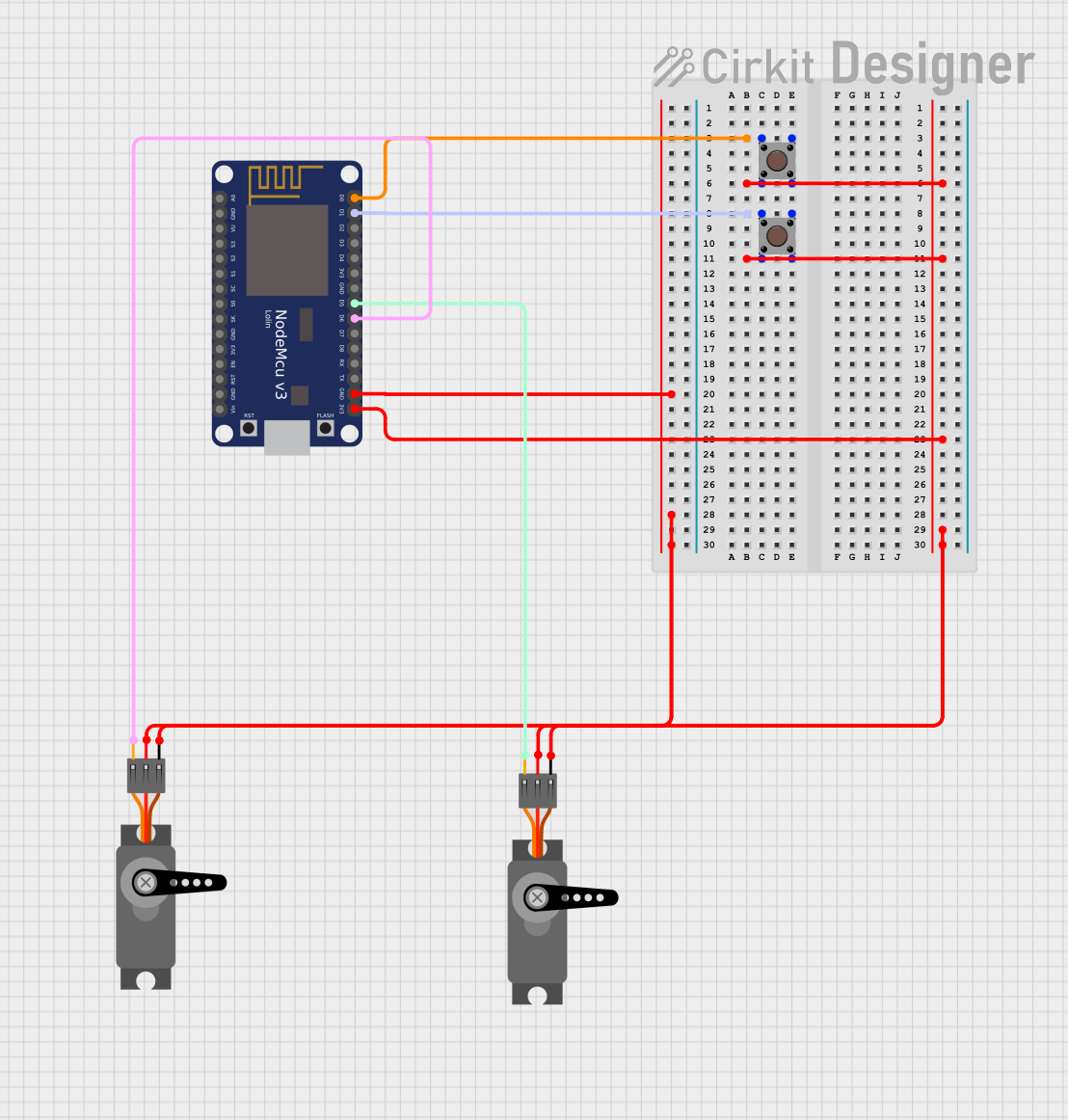 Open Project in Cirkit Designer
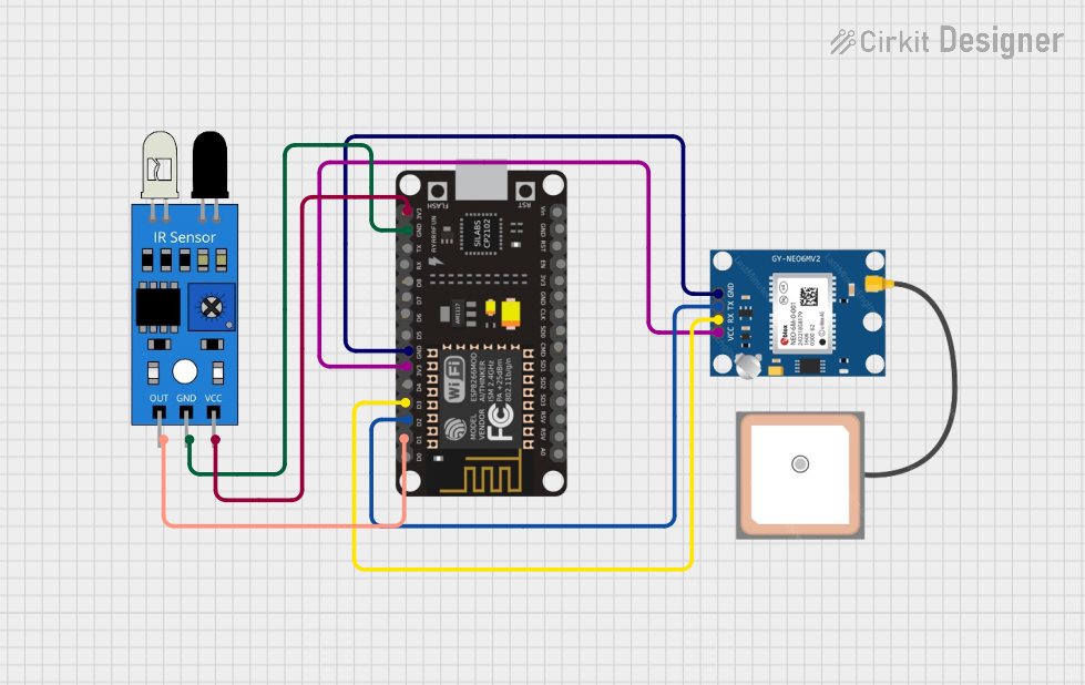 Open Project in Cirkit Designer
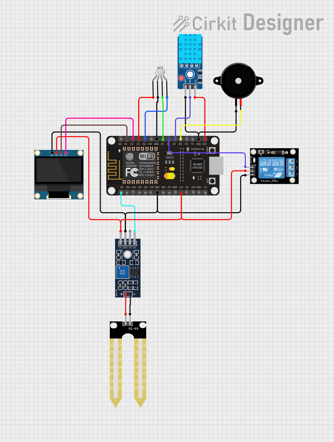 Open Project in Cirkit Designer
Explore Projects Built with NodeMCU 32 38 Pin
Open Project in Cirkit DesignerOpen Project in Cirkit DesignerOpen Project in Cirkit DesignerOpen Project in Cirkit DesignerCommon Applications and Use Cases
- IoT (Internet of Things) devices and systems
- Home automation and smart appliances
- Wireless sensor networks
- Remote monitoring and control
- Prototyping and development of embedded systems
- Bluetooth Low Energy (BLE) applications
Technical Specifications
Key Technical Details
| Parameter | Specification |
|---|---|
| Microcontroller | ESP32 Dual-Core Tensilica Xtensa LX6 |
| Operating Voltage | 3.3V |
| Input Voltage Range | 5V (via USB) or 7-12V (via VIN pin) |
| Flash Memory | 4MB |
| SRAM | 520KB |
| Wi-Fi Standard | 802.11 b/g/n |
| Bluetooth | BLE and Bluetooth v4.2 |
| GPIO Pins | 30 (including ADC, DAC, PWM, I2C, SPI, UART) |
| ADC Resolution | 12-bit |
| DAC Resolution | 8-bit |
| Clock Speed | Up to 240 MHz |
| Power Consumption | Ultra-low power (varies by mode) |
| Dimensions | 58mm x 25.5mm |
Pin Configuration and Descriptions
The NodeMCU 32 38 Pin module has 38 pins, each with specific functions. Below is the pinout description:
| Pin Number | Pin Name | Function Description |
|---|---|---|
| 1 | GND | Ground |
| 2 | VIN | Input voltage (7-12V) |
| 3 | 3V3 | 3.3V output for powering external devices |
| 4-21 | GPIO0-19 | General Purpose Input/Output pins |
| 22 | ADC1_CH0 | Analog-to-Digital Converter channel 0 |
| 23 | ADC1_CH1 | Analog-to-Digital Converter channel 1 |
| 24 | DAC1 | Digital-to-Analog Converter channel 1 |
| 25 | DAC2 | Digital-to-Analog Converter channel 2 |
| 26 | TX0 | UART Transmit pin |
| 27 | RX0 | UART Receive pin |
| 28 | EN | Enable pin (active high) |
| 29 | IO34 | Input-only GPIO |
| 30 | IO35 | Input-only GPIO |
| 31-38 | Reserved | Reserved for future use |
Usage Instructions
How to Use the Component in a Circuit
Powering the NodeMCU 32 38 Pin:
- Connect the VIN pin to a 7-12V power source or use the USB port for 5V input.
- Ensure the GND pin is connected to the ground of your circuit.
Programming the Module:
- Use the Arduino IDE or ESP-IDF (Espressif IoT Development Framework) to program the module.
- Install the ESP32 board package in the Arduino IDE via the Board Manager.
Connecting Peripherals:
- Use GPIO pins for digital input/output.
- Connect sensors to ADC pins for analog input.
- Use I2C, SPI, or UART interfaces for communication with external devices.
Uploading Code:
- Connect the NodeMCU 32 38 Pin to your computer via a USB cable.
- Select the correct board and port in the Arduino IDE.
- Upload your code to the module.
Important Considerations and Best Practices
- Always use a level shifter when interfacing 5V devices with the 3.3V GPIO pins.
- Avoid drawing more than 500mA from the 3V3 pin to prevent damage.
- Use proper decoupling capacitors to stabilize the power supply.
- Ensure the antenna area is not obstructed for optimal Wi-Fi and Bluetooth performance.
Example Code for Arduino UNO Integration
Below is an example of how to use the NodeMCU 32 38 Pin to read data from a DHT11 temperature and humidity sensor and send it to the serial monitor:
#include <DHT.h>

// Define the DHT sensor type and pin
#define DHTPIN 4       // GPIO4 is connected to the DHT11 data pin
#define DHTTYPE DHT11  // DHT11 sensor

DHT dht(DHTPIN, DHTTYPE);

void setup() {
  Serial.begin(115200); // Initialize serial communication at 115200 baud
  dht.begin();          // Initialize the DHT sensor
  Serial.println("DHT11 Sensor Test");
}

void loop() {
  delay(2000); // Wait 2 seconds between readings

  // Read temperature and humidity values
  float humidity = dht.readHumidity();
  float temperature = dht.readTemperature();

  // Check if the readings are valid
  if (isnan(humidity) || isnan(temperature)) {
    Serial.println("Failed to read from DHT sensor!");
    return;
  }

  // Print the readings to the serial monitor
  Serial.print("Humidity: ");
  Serial.print(humidity);
  Serial.print("%  Temperature: ");
  Serial.print(temperature);
  Serial.println("°C");
}
Troubleshooting and FAQs
Common Issues Users Might Face
Module Not Detected by Computer:
- Ensure the USB cable is functional and supports data transfer.
- Install the correct USB-to-serial driver (e.g., CP2102 or CH340).
Code Upload Fails:
- Check that the correct board and port are selected in the Arduino IDE.
- Press and hold the "BOOT" button on the module while uploading the code.
Wi-Fi Connection Issues:
- Verify the SSID and password in your code.
- Ensure the router is within range and supports 2.4GHz Wi-Fi.
Unstable Power Supply:
- Use a stable power source with sufficient current capacity (at least 500mA).
Solutions and Tips for Troubleshooting
- Use the serial monitor to debug and identify issues in your code.
- Double-check all connections and ensure there are no loose wires.
- Update the ESP32 board package in the Arduino IDE to the latest version.
- Refer to the ESP32 datasheet for advanced debugging and troubleshooting.