How to Use IO Expansion Sheild V7.1: Examples, Pinouts, and Specs
Introduction
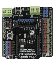
The IO Expansion Shield V7.1 (Manufacturer Part ID: DFR0265) by DFRobot is a versatile add-on board designed to expand the input/output capabilities of microcontrollers, such as the Arduino UNO. This shield provides additional GPIO pins, analog inputs, and communication interfaces, making it an essential tool for prototyping and building complex projects. It simplifies the connection of sensors, actuators, and other peripherals, reducing wiring complexity and improving project reliability.
Explore Projects Built with IO Expansion Sheild V7.1
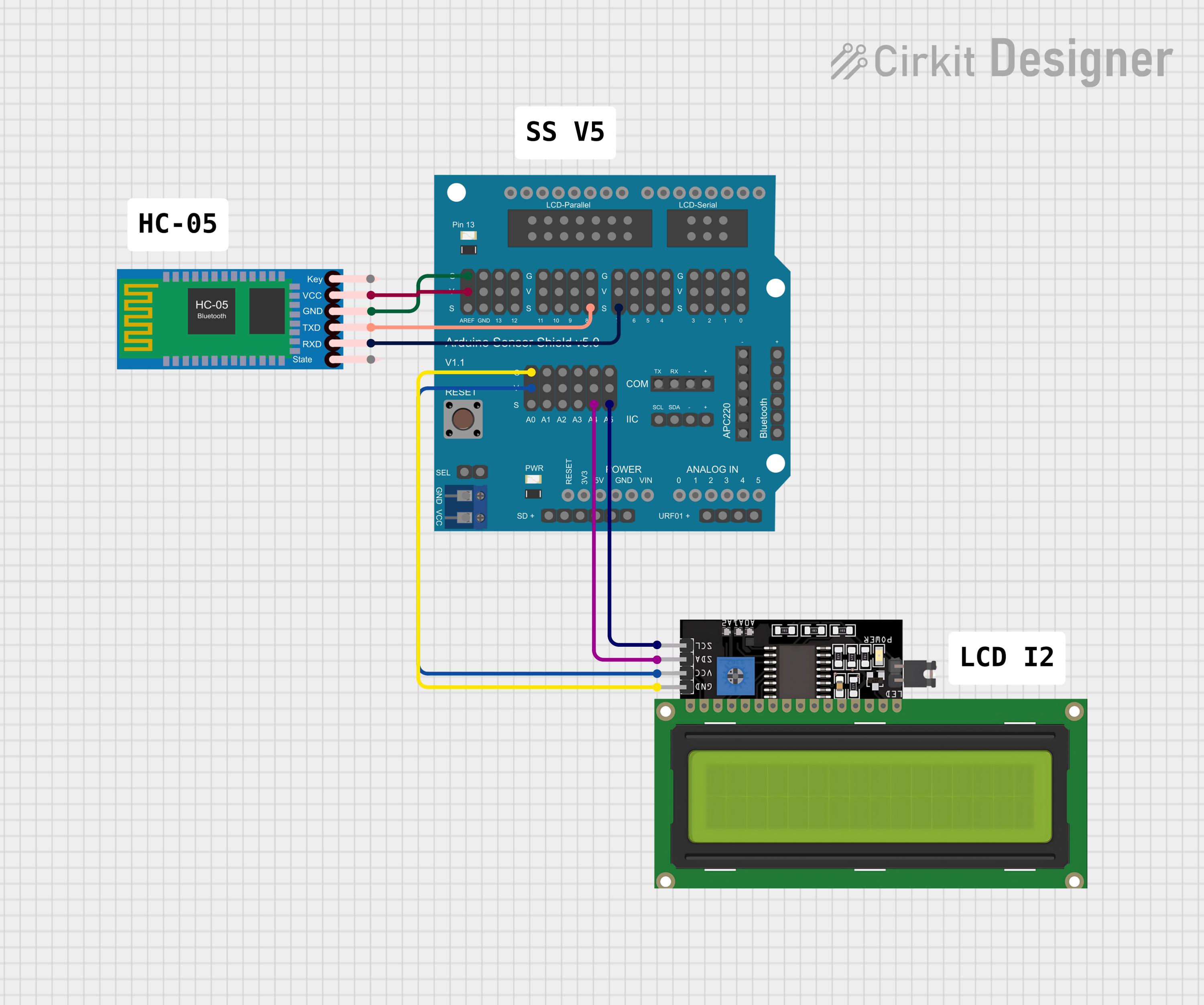
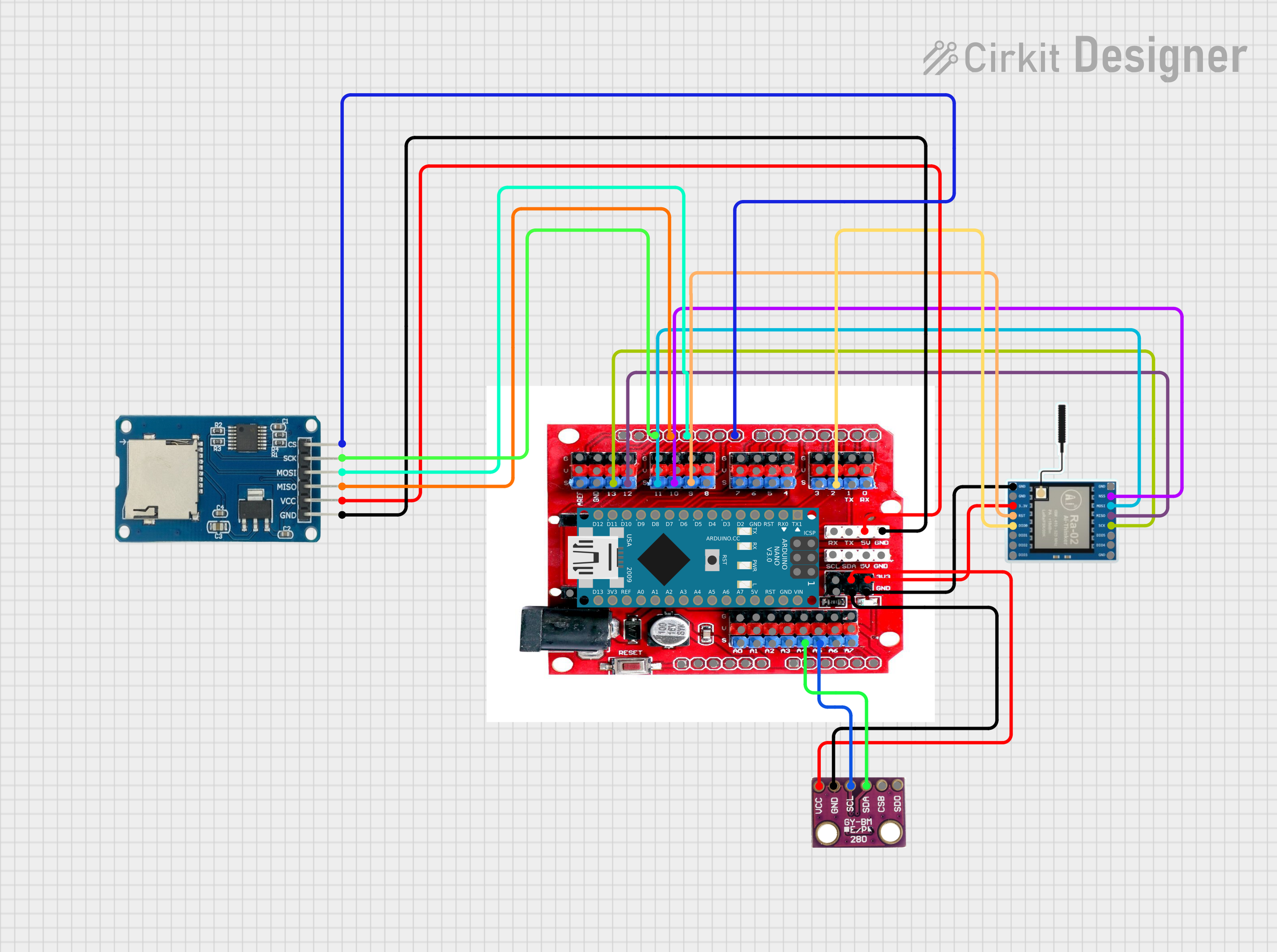


Explore Projects Built with IO Expansion Sheild V7.1
Common Applications and Use Cases
- Robotics: Connecting multiple sensors, motors, and actuators.
- IoT Projects: Adding communication modules like Bluetooth, Wi-Fi, or GSM.
- Prototyping: Simplifying the integration of various electronic components.
- Educational Projects: Teaching electronics and programming with ease.
Technical Specifications
The following table outlines the key technical details of the IO Expansion Shield V7.1:
| Specification | Details |
|---|---|
| Manufacturer | DFRobot |
| Part Number | DFR0265 |
| Compatible Microcontrollers | Arduino UNO, Mega, Leonardo, and other Arduino-compatible boards |
| Operating Voltage | 5V (from Arduino board) |
| Communication Interfaces | UART, I2C, SPI |
| GPIO Pins | 14 digital I/O pins (6 PWM capable) |
| Analog Inputs | 6 analog input pins |
| Power Output Pins | 5V and 3.3V power output for external modules |
| Dimensions | 68.6mm x 53.4mm (standard Arduino shield size) |
Pin Configuration and Descriptions
The IO Expansion Shield V7.1 provides easy access to the Arduino's pins and additional features. Below is the pin configuration:
| Pin | Description |
|---|---|
| Digital Pins | D0-D13: Standard digital I/O pins, with PWM support on D3, D5, D6, D9, D10, D11 |
| Analog Pins | A0-A5: Analog input pins |
| UART | TX (D1) and RX (D0): Serial communication |
| I2C | SDA (A4) and SCL (A5): I2C communication |
| SPI | D10 (SS), D11 (MOSI), D12 (MISO), D13 (SCK): SPI communication |
| Power Pins | 5V, 3.3V, GND: Power output for external modules |
| Reset | Reset button to restart the microcontroller |
Usage Instructions
How to Use the IO Expansion Shield V7.1 in a Circuit
- Attach the Shield: Place the IO Expansion Shield V7.1 on top of your Arduino board, ensuring the pins align correctly.
- Connect Peripherals: Use the labeled headers to connect sensors, actuators, or communication modules.
- Power the Shield: The shield draws power directly from the Arduino board. Ensure your Arduino is powered via USB or an external power source.
- Program the Arduino: Write and upload your Arduino sketch using the Arduino IDE.
Important Considerations and Best Practices
- Voltage Compatibility: Ensure connected peripherals are compatible with the 5V or 3.3V power outputs.
- Avoid Overloading: Do not exceed the current limits of the Arduino board when powering external devices.
- Pin Conflicts: Be mindful of pin usage, especially when using communication interfaces like UART, I2C, or SPI.
- Secure Connections: Use jumper wires or connectors to ensure stable connections to the shield.
Example: Connecting an LED and a Button
Below is an example of how to use the IO Expansion Shield V7.1 to control an LED with a button:
Circuit Setup
- Connect the LED's positive leg to D13 and the negative leg to GND.
- Connect one side of the button to D2 and the other side to GND.
Arduino Code
// Define pin numbers for the LED and button
const int ledPin = 13;  // LED connected to digital pin 13
const int buttonPin = 2; // Button connected to digital pin 2

void setup() {
  pinMode(ledPin, OUTPUT);  // Set LED pin as output
  pinMode(buttonPin, INPUT_PULLUP); // Set button pin as input with pull-up resistor
}

void loop() {
  // Read the button state
  int buttonState = digitalRead(buttonPin);

  // If the button is pressed, turn on the LED
  if (buttonState == LOW) { // LOW means the button is pressed
    digitalWrite(ledPin, HIGH); // Turn on the LED
  } else {
    digitalWrite(ledPin, LOW);  // Turn off the LED
  }
}
Troubleshooting and FAQs
Common Issues and Solutions
Shield Not Detected by Arduino
- Solution: Ensure the shield is properly seated on the Arduino board. Check for bent or misaligned pins.
Peripherals Not Working
- Solution: Verify the connections and ensure the correct pins are used in your code. Check the power requirements of the connected devices.
Communication Interfaces Not Responding
- Solution: Ensure no pin conflicts exist. For example, avoid using D0 and D1 for other purposes when using UART.
Arduino Not Powering the Shield
- Solution: Check the Arduino's power source. Use an external power supply if necessary.
FAQs
Q: Can I use the IO Expansion Shield V7.1 with boards other than Arduino UNO?
A: Yes, the shield is compatible with Arduino Mega, Leonardo, and other Arduino-compatible boards.
Q: Does the shield support 3.3V devices?
A: Yes, the shield provides a 3.3V power output for peripherals.
Q: Can I stack other shields on top of the IO Expansion Shield V7.1?
A: Yes, the shield supports stacking, but ensure there are no pin conflicts between shields.
Q: How do I reset the Arduino while using the shield?
A: Use the reset button on the shield to restart the Arduino.
This concludes the documentation for the IO Expansion Shield V7.1. For further assistance, refer to the DFRobot website or community forums.