How to Use LTC 3780 AUTO DC BUCK BOOST: Examples, Pinouts, and Specs
Introduction
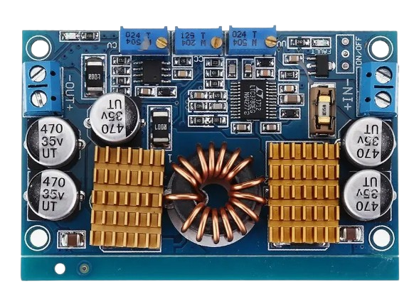
The LTC 3780 is a high-efficiency DC-DC converter capable of operating as both a buck (step-down) and boost (step-up) regulator. It is designed to provide a stable output voltage from a varying input voltage, making it ideal for applications where the input voltage may fluctuate above or below the desired output voltage. This versatility makes the LTC 3780 a popular choice for battery-powered devices, solar power systems, automotive electronics, and other scenarios requiring efficient voltage regulation.
Explore Projects Built with LTC 3780 AUTO DC BUCK BOOST


Explore Projects Built with LTC 3780 AUTO DC BUCK BOOST
Common Applications and Use Cases
- Battery-powered devices (e.g., laptops, portable electronics)
- Solar power systems for voltage regulation
- Automotive electronics for stable power delivery
- Industrial power supplies
- LED drivers and lighting systems
- Uninterruptible power supplies (UPS)
Technical Specifications
The following are the key technical details of the LTC 3780 DC-DC converter:
| Parameter | Value |
|---|---|
| Input Voltage Range | 4V to 36V |
| Output Voltage Range | 0.8V to 30V |
| Output Current | Up to 10A (depending on external components and thermal management) |
| Efficiency | Up to 98% |
| Switching Frequency | Adjustable from 200kHz to 400kHz |
| Operating Temperature Range | -40°C to 125°C |
| Control Mode | Current-mode control |
| Protection Features | Overcurrent protection, thermal shutdown, and short-circuit protection |
Pin Configuration and Descriptions
The LTC 3780 is typically available in a 16-pin package. Below is the pin configuration and description:
| Pin Number | Pin Name | Description |
|---|---|---|
| 1 | VIN | Input voltage pin. Connect to the input power source. |
| 2 | VOUT | Output voltage pin. Connect to the load. |
| 3 | GND | Ground pin. Connect to the system ground. |
| 4 | FB | Feedback pin. Used to set the output voltage via a resistor divider. |
| 5 | COMP | Compensation pin. Connect to an external RC network for stability. |
| 6 | ITH | Current threshold pin. Used for current-mode control. |
| 7 | SW | Switch pin. Connect to the inductor and diode. |
| 8 | BOOST | Boost pin. Connect to a capacitor for high-side gate drive. |
| 9 | INTVCC | Internal voltage regulator output. Provides power to internal circuitry. |
| 10 | RUN/SS | Run/soft-start pin. Used to enable the IC and control soft-start functionality. |
| 11 | PGND | Power ground pin. Connect to the system ground. |
| 12 | SYNC | Synchronization pin. Used to synchronize the switching frequency. |
| 13 | FREQ | Frequency pin. Connect to a resistor to set the switching frequency. |
| 14 | MODE | Mode selection pin. Used to select between Burst Mode and continuous operation. |
| 15 | VCC | Supply voltage pin for the internal circuitry. |
| 16 | EXTVCC | External voltage input for powering the IC. |
Usage Instructions
How to Use the LTC 3780 in a Circuit
Input and Output Connections:
- Connect the input voltage source to the VIN pin.
- Connect the load to the VOUT pin.
- Ensure proper grounding by connecting the GND and PGND pins to the system ground.
Setting the Output Voltage:
- Use a resistor divider network connected to the FB pin to set the desired output voltage.
- The output voltage can be calculated using the formula:
[ V_{OUT} = V_{REF} \times \left(1 + \frac{R1}{R2}\right) ]
where ( V_{REF} ) is typically 0.8V.
Switching Frequency:
- Connect a resistor to the FREQ pin to set the switching frequency. Refer to the datasheet for the resistor value corresponding to the desired frequency.
Soft-Start:
- Use the RUN/SS pin to enable the IC and control the soft-start time by connecting a capacitor to this pin.
Inductor and Capacitor Selection:
- Choose an inductor with sufficient current rating and low DC resistance for optimal efficiency.
- Use low-ESR capacitors for input and output filtering to minimize voltage ripple.
Thermal Management:
- Ensure proper heat dissipation by using a heatsink or placing the IC on a PCB with adequate thermal vias.
Example: Using the LTC 3780 with an Arduino UNO
The LTC 3780 can be used to power an Arduino UNO from a variable input voltage source. Below is an example of Arduino code to monitor the output voltage using the ADC pin:
// Define the analog pin connected to the output voltage divider
const int voltagePin = A0;

// Define the reference voltage and resistor divider values
const float referenceVoltage = 5.0; // Arduino ADC reference voltage
const float R1 = 10000.0;           // Resistor R1 in the voltage divider (in ohms)
const float R2 = 2000.0;            // Resistor R2 in the voltage divider (in ohms)

void setup() {
  Serial.begin(9600); // Initialize serial communication
}

void loop() {
  int adcValue = analogRead(voltagePin); // Read the ADC value
  float voltage = (adcValue * referenceVoltage / 1023.0) * ((R1 + R2) / R2);

  // Print the output voltage to the serial monitor
  Serial.print("Output Voltage: ");
  Serial.print(voltage);
  Serial.println(" V");

  delay(1000); // Wait for 1 second before the next reading
}
Important Considerations and Best Practices
- Always verify the input and output voltage ranges to ensure they are within the component's specifications.
- Use proper decoupling capacitors near the VIN and VOUT pins to reduce noise.
- Avoid exceeding the maximum current rating to prevent damage to the IC.
- Ensure proper PCB layout with short and wide traces for high-current paths.
Troubleshooting and FAQs
Common Issues and Solutions
Output Voltage is Unstable:
- Check the feedback resistor network for proper values.
- Ensure the compensation network (COMP pin) is correctly configured.
Excessive Heat Generation:
- Verify that the input and output currents are within the IC's limits.
- Improve thermal management by adding a heatsink or increasing PCB copper area.
No Output Voltage:
- Ensure the RUN/SS pin is properly enabled.
- Check for short circuits or incorrect connections in the circuit.
High Output Ripple:
- Use low-ESR capacitors for input and output filtering.
- Verify the inductor value and ensure it meets the design requirements.
FAQs
Q: Can the LTC 3780 handle reverse polarity on the input?
A: No, the LTC 3780 does not have built-in reverse polarity protection. Use an external diode or MOSFET for protection.
Q: What is the maximum output current the LTC 3780 can provide?
A: The maximum output current depends on the external components and thermal management. Typically, it can provide up to 10A with proper design.
Q: Can the LTC 3780 operate without a load?
A: Yes, the LTC 3780 can operate without a load, but ensure the feedback network is properly configured to maintain stability.
Q: How do I synchronize the switching frequency?
A: Use the SYNC pin to synchronize the LTC 3780 with an external clock signal.
By following this documentation, users can effectively integrate the LTC 3780 into their projects and troubleshoot common issues.