Cirkit Designer Logo
Cirkit Designer
Your all-in-one circuit design IDE
Home / 
Component Documentation

How to Use MAG3110: Examples, Pinouts, and Specs

Image of MAG3110
Cirkit Designer LogoDesign with MAG3110 in Cirkit Designer

Introduction

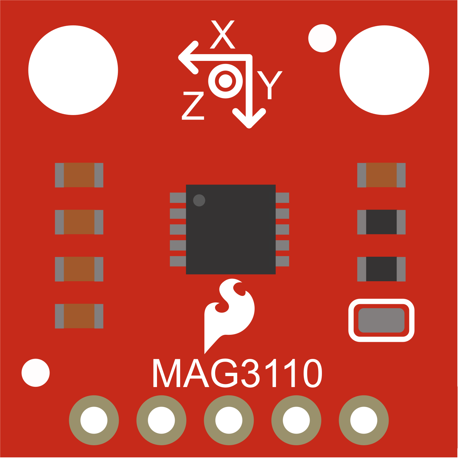
The MAG3110 is a small, low-power, digital 3-axis magnetometer with a wide dynamic range to measure magnetic field data. This sensor can be used for applications such as compass navigation, position tracking, and motion sensing.

Explore Projects Built with MAG3110

Use Cirkit Designer to design, explore, and prototype these projects online. Some projects support real-time simulation. Click "Open Project" to start designing instantly!
Battery-Powered Arduino Nano Weather Station with LoRa and SD Card Storage
Image of CanSat: A project utilizing MAG3110 in a practical application
This circuit is a multi-sensor data acquisition system powered by an 18650 Li-ion battery and managed by two Arduino Nano microcontrollers. It includes various sensors such as BMP280, ADXL345, AMG8833, MAG3110, and OV7670 for environmental and motion data, as well as a LoRa module for wireless communication, an SD card module for data storage, and LEDs and a piezo buzzer for status indication.
Cirkit Designer LogoOpen Project in Cirkit Designer
Battery-Powered Raspberry Pi Pico GPS Tracker with Sensor Integration
Image of Copy of CanSet v1: A project utilizing MAG3110 in a practical application
This circuit is a data acquisition and communication system powered by a LiPoly battery and managed by a Raspberry Pi Pico. It includes sensors (BMP280, MPU9250) for environmental data, a GPS module for location tracking, an SD card for data storage, and a WLR089-CanSAT for wireless communication. The TP4056 module handles battery charging, and a toggle switch controls power distribution.
Cirkit Designer LogoOpen Project in Cirkit Designer
ESP32-Based Battery-Powered Multi-Sensor System
Image of Dive sense: A project utilizing MAG3110 in a practical application
This circuit consists of a TP4056 module connected to a 3.7V LiPo battery, providing a charging interface for the battery. The TP4056 manages the charging process by connecting its B+ and B- pins to the battery's positive and ground terminals, respectively.
Cirkit Designer LogoOpen Project in Cirkit Designer
Arduino Mega 2560 Based Security System with Fingerprint Authentication and SMS Alerts
Image of Door security system: A project utilizing MAG3110 in a practical application
This circuit features an Arduino Mega 2560 microcontroller interfaced with a SIM800L GSM module, two fingerprint scanners, an I2C LCD display, an IR sensor, and a piezo buzzer. Power management is handled by a PowerBoost 1000 Basic Pad USB, a TP4056 charging module, and a Li-ion 18650 battery, with an option to use a Mini AC-DC 110V-230V to 5V 700mA module for direct power supply. The primary functionality appears to be a security system with GSM communication capabilities, biometric access control, and visual/audible feedback.
Cirkit Designer LogoOpen Project in Cirkit Designer

Explore Projects Built with MAG3110

Use Cirkit Designer to design, explore, and prototype these projects online. Some projects support real-time simulation. Click "Open Project" to start designing instantly!
Image of CanSat: A project utilizing MAG3110 in a practical application
Battery-Powered Arduino Nano Weather Station with LoRa and SD Card Storage
This circuit is a multi-sensor data acquisition system powered by an 18650 Li-ion battery and managed by two Arduino Nano microcontrollers. It includes various sensors such as BMP280, ADXL345, AMG8833, MAG3110, and OV7670 for environmental and motion data, as well as a LoRa module for wireless communication, an SD card module for data storage, and LEDs and a piezo buzzer for status indication.
Cirkit Designer LogoOpen Project in Cirkit Designer
Image of Copy of CanSet v1: A project utilizing MAG3110 in a practical application
Battery-Powered Raspberry Pi Pico GPS Tracker with Sensor Integration
This circuit is a data acquisition and communication system powered by a LiPoly battery and managed by a Raspberry Pi Pico. It includes sensors (BMP280, MPU9250) for environmental data, a GPS module for location tracking, an SD card for data storage, and a WLR089-CanSAT for wireless communication. The TP4056 module handles battery charging, and a toggle switch controls power distribution.
Cirkit Designer LogoOpen Project in Cirkit Designer
Image of Dive sense: A project utilizing MAG3110 in a practical application
ESP32-Based Battery-Powered Multi-Sensor System
This circuit consists of a TP4056 module connected to a 3.7V LiPo battery, providing a charging interface for the battery. The TP4056 manages the charging process by connecting its B+ and B- pins to the battery's positive and ground terminals, respectively.
Cirkit Designer LogoOpen Project in Cirkit Designer
Image of Door security system: A project utilizing MAG3110 in a practical application
Arduino Mega 2560 Based Security System with Fingerprint Authentication and SMS Alerts
This circuit features an Arduino Mega 2560 microcontroller interfaced with a SIM800L GSM module, two fingerprint scanners, an I2C LCD display, an IR sensor, and a piezo buzzer. Power management is handled by a PowerBoost 1000 Basic Pad USB, a TP4056 charging module, and a Li-ion 18650 battery, with an option to use a Mini AC-DC 110V-230V to 5V 700mA module for direct power supply. The primary functionality appears to be a security system with GSM communication capabilities, biometric access control, and visual/audible feedback.
Cirkit Designer LogoOpen Project in Cirkit Designer

Common Applications and Use Cases

  • Electronic compasses
  • Map rotation in smartphones and tablets
  • Position detection in consumer electronics
  • Motion detection for gaming and virtual reality input devices

Technical Specifications

Key Technical Details

  • Supply Voltage (VDD): 1.95V to 3.6V
  • Measurement Range: ±1000 µT
  • Sensitivity: 0.1 µT
  • Output Data Rate (ODR): 0.133 to 80 Hz
  • Interface: I2C, up to 400 kHz
  • Operating Temperature: -40°C to +85°C

Pin Configuration and Descriptions

Pin Number Name Description
1 VDD Power supply voltage
2 GND Ground connection
3 SCL I2C clock line
4 SDA I2C data line
5 DRDY Data ready output (active low)
6 INT Interrupt output (active low)

Usage Instructions

How to Use the MAG3110 in a Circuit

  1. Power Supply: Connect VDD to a 1.95V to 3.6V power source and GND to the ground.
  2. I2C Communication: Connect SCL and SDA to the I2C clock and data lines, respectively. Ensure pull-up resistors are in place as required for your microcontroller's I2C bus.
  3. Data Ready (DRDY): Optionally, connect DRDY to a digital input on your microcontroller if you wish to use the data ready feature.
  4. Interrupt (INT): Optionally, connect INT to a digital input on your microcontroller if you wish to use the interrupt feature.

Important Considerations and Best Practices

  • Ensure that the power supply is stable and within the specified voltage range.
  • Place the magnetometer away from magnetic interference sources such as speakers and motors.
  • Calibrate the magnetometer in the final design to account for any local magnetic distortions.
  • Use proper decoupling capacitors close to the power pins of the MAG3110 to filter out noise.

Troubleshooting and FAQs

Common Issues

  • No Data on I2C: Check connections and pull-up resistors on the I2C lines. Ensure that the correct I2C address is being used.
  • Inaccurate Readings: Verify that the device is calibrated and that there are no nearby magnetic interference sources.

Solutions and Tips for Troubleshooting

  • If the MAG3110 is not responding, check the power supply and I2C connections.
  • For inaccurate readings, recalibrate the sensor and make sure it is placed in a magnetically clean environment.

FAQs

Q: How do I calibrate the MAG3110? A: Calibration typically involves taking several measurements at known orientations and then using these to correct for offsets and scale factors.

Q: Can the MAG3110 be used for precise navigation? A: While the MAG3110 can be used for basic navigation, its accuracy is subject to environmental factors and may not be suitable for precision navigation without additional sensors and algorithms.

Example Code for Arduino UNO

Below is an example of how to interface the MAG3110 with an Arduino UNO. This code initializes the sensor and reads the magnetic field data.

#include <Wire.h>

// MAG3110 I2C address
#define MAG3110_ADDRESS 0x0E

// Register addresses
#define MAG3110_DR_STATUS 0x00
#define MAG3110_OUT_X_MSB 0x01
#define MAG3110_WHO_AM_I  0x07
#define MAG3110_CTRL_REG1 0x10

void setup() {
  Wire.begin(); // Initialize I2C
  Serial.begin(9600); // Start serial for output
  
  // Check device ID
  if (readRegister(MAG3110_WHO_AM_I) != 0xC4) {
    Serial.println("MAG3110 not found");
    while (1);
  }
  
  // Set up the sensor
  writeRegister(MAG3110_CTRL_REG1, 0x01); // Active mode
}

void loop() {
  // Check if data is ready
  if (readRegister(MAG3110_DR_STATUS) & 0x01) {
    int x, y, z;
    // Read the magnetometer data
    x = readMagData(MAG3110_OUT_X_MSB);
    y = readMagData(MAG3110_OUT_X_MSB + 2);
    z = readMagData(MAG3110_OUT_X_MSB + 4);
    
    // Print the values
    Serial.print("X: "); Serial.print(x); Serial.print(" ");
    Serial.print("Y: "); Serial.print(y); Serial.print(" ");
    Serial.print("Z: "); Serial.println(z);
  }
  
  delay(100); // Wait before reading again
}

// Function to write to a register
void writeRegister(byte reg, byte value) {
  Wire.beginTransmission(MAG3110_ADDRESS);
  Wire.write(reg);
  Wire.write(value);
  Wire.endTransmission();
}

// Function to read a byte from a register
byte readRegister(byte reg) {
  Wire.beginTransmission(MAG3110_ADDRESS);
  Wire.write(reg);
  Wire.endTransmission();
  Wire.requestFrom(MAG3110_ADDRESS, 1);
  return Wire.read();
}

// Function to read two bytes from consecutive registers and combine them
int readMagData(byte reg) {
  Wire.beginTransmission(MAG3110_ADDRESS);
  Wire.write(reg);
  Wire.endTransmission();
  Wire.requestFrom(MAG3110_ADDRESS, 2);
  int value = Wire.read() << 8;
  value |= Wire.read();
  return value;
}

This code is a basic starting point for using the MAG3110 with an Arduino. It demonstrates initialization, reading from the sensor, and outputting the data. For a complete application, additional code for calibration and data processing would be necessary.