How to Use XT90 panel mounted: Examples, Pinouts, and Specs
Introduction
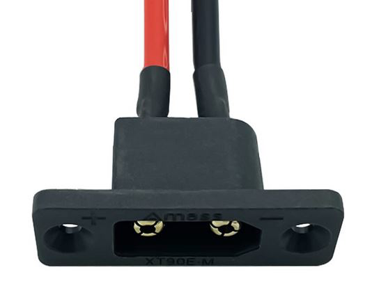
The XT90 panel mounted connector is a high-current electrical connector designed for reliable and secure power connections. It is widely used in applications requiring high current handling, such as RC vehicles, drones, electric bikes, and other high-power systems. Its robust design, secure locking mechanism, and panel-mounting capability make it an excellent choice for both professional and hobbyist projects.
Explore Projects Built with XT90 panel mounted


Explore Projects Built with XT90 panel mounted
Common Applications and Use Cases
- RC vehicles (cars, boats, and planes)
- Drones and UAVs
- Electric bikes and scooters
- High-power battery packs
- Solar power systems
- Industrial equipment requiring high-current connections
Technical Specifications
Key Technical Details
- Rated Current: 90A continuous
- Rated Voltage: Up to 500V DC
- Contact Resistance: ≤ 0.6 mΩ
- Material: Gold-plated copper contacts, nylon housing
- Temperature Range: -20°C to 120°C
- Wire Gauge Compatibility: 10-12 AWG
- Mounting Style: Panel-mounted with screws
- Locking Mechanism: Snap-fit design for secure connections
Pin Configuration and Descriptions
The XT90 panel mounted connector consists of two main terminals: positive (+) and negative (-). These terminals are clearly marked on the connector housing to ensure proper polarity during installation.
| Pin | Description | Notes |
|---|---|---|
| Positive (+) | Positive terminal for power | Connect to the positive side of the circuit or battery. |
| Negative (-) | Negative terminal for power | Connect to the negative side of the circuit or battery. |
Dimensions
- Connector Size: 21.6mm x 29.0mm x 8.5mm (approx.)
- Panel Cutout: 24mm x 12mm (rectangular opening for mounting)
Usage Instructions
How to Use the XT90 Panel Mounted Connector in a Circuit
Prepare the Wires:
- Strip the insulation from the wires to expose about 5-7mm of the conductor.
- Use 10-12 AWG wires for optimal performance.
Solder the Wires:
- Tin the exposed wire ends with solder to ensure a strong connection.
- Insert the tinned wire ends into the connector's solder cups.
- Heat the solder cups with a soldering iron and apply solder to secure the wires.
Mount the Connector:
- Cut a rectangular opening in the panel (24mm x 12mm) where the connector will be installed.
- Insert the connector into the opening and secure it using screws or bolts.
Connect to the Circuit:
- Ensure proper polarity by connecting the positive and negative terminals to the corresponding points in the circuit.
- Snap the male and female XT90 connectors together to establish a secure connection.
Important Considerations and Best Practices
- Polarity Check: Always double-check the polarity markings on the connector to avoid reverse polarity, which can damage your circuit.
- Soldering Temperature: Use a soldering iron with a temperature of 350-400°C for efficient soldering without damaging the connector.
- Wire Gauge: Use the recommended wire gauge (10-12 AWG) to handle the rated current without overheating.
- Secure Mounting: Ensure the connector is firmly mounted to the panel to prevent movement or stress on the wires.
- Avoid Overcurrent: Do not exceed the rated current of 90A to prevent overheating or damage to the connector.
Example: Connecting to an Arduino UNO
While the XT90 connector is not directly used with low-power devices like the Arduino UNO, it can be part of a power delivery system for high-current peripherals. For example, you can use the XT90 connector to supply power to a motor driver or other high-power components in an Arduino-based project.
// Example: Controlling a motor driver powered via an XT90 connector
// This code assumes the motor driver is connected to the Arduino UNO.

const int motorPin = 9; // PWM pin connected to the motor driver

void setup() {
  pinMode(motorPin, OUTPUT); // Set motor pin as output
}

void loop() {
  analogWrite(motorPin, 128); // Run motor at 50% speed
  delay(5000); // Keep motor running for 5 seconds

  analogWrite(motorPin, 0); // Stop the motor
  delay(2000); // Wait for 2 seconds before restarting
}
Note: Ensure the motor driver and other high-power components are properly powered via the XT90 connector, and the Arduino is powered separately to avoid overloading.
Troubleshooting and FAQs
Common Issues and Solutions
| Issue | Possible Cause | Solution |
|---|---|---|
| Connector gets hot during operation | Exceeding the rated current or poor soldering | Ensure current is ≤ 90A and check solder joints. |
| Loose connection between male and female | Dirt or debris in the connector | Clean the connector with isopropyl alcohol. |
| Reverse polarity connection | Incorrect wiring | Double-check polarity markings before connecting. |
| Difficulty mounting the connector | Incorrect panel cutout size | Ensure the cutout matches the specified dimensions (24mm x 12mm). |
FAQs
Can the XT90 connector handle currents above 90A?
- No, the XT90 is rated for a maximum continuous current of 90A. Exceeding this limit can cause overheating and damage.
Is the XT90 connector waterproof?
- The standard XT90 connector is not waterproof. For outdoor or wet environments, consider using a waterproof housing or a specialized waterproof XT90 variant.
Can I use thinner wires with the XT90 connector?
- It is not recommended to use wires thinner than 12 AWG, as they may not handle the rated current safely.
How do I disconnect the XT90 connector?
- Press the locking tabs on the sides of the connector and gently pull the male and female parts apart.
By following this documentation, you can effectively use the XT90 panel mounted connector in your high-power applications.