
How to Use Step-down converter DC-DC: Examples, Pinouts, and Specs
 Design with Step-down converter DC-DC in Cirkit Designer
Introduction
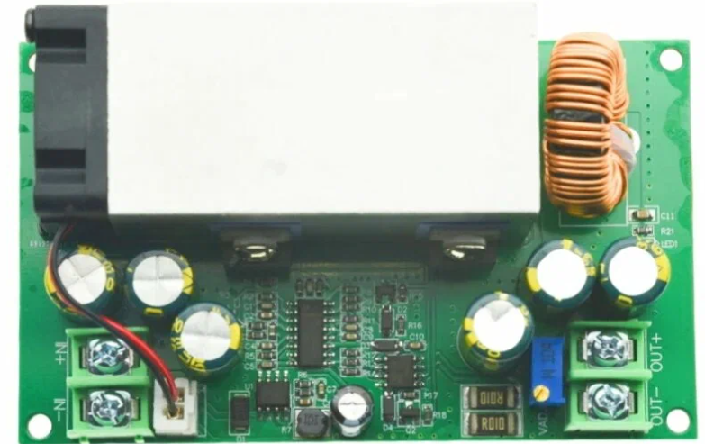
A step-down converter, also known as a buck converter, is a type of DC-DC converter that reduces the input voltage to a lower output voltage while maintaining high efficiency. It is widely used in power supply applications to provide a stable voltage to electronic devices. These converters are essential in battery-powered systems, embedded systems, and other applications where efficient voltage regulation is required.
Explore Projects Built with Step-down converter DC-DC
 Open Project in Cirkit Designer
 Open Project in Cirkit Designer
 Open Project in Cirkit Designer
 Open Project in Cirkit Designer
Explore Projects Built with Step-down converter DC-DC
Open Project in Cirkit DesignerOpen Project in Cirkit DesignerOpen Project in Cirkit DesignerOpen Project in Cirkit DesignerCommon Applications and Use Cases
- Powering microcontrollers and sensors in embedded systems
- Voltage regulation for battery-powered devices
- Supplying stable voltage to LEDs and other low-voltage components
- Powering communication modules (e.g., Wi-Fi, Bluetooth)
- Industrial and automotive electronics
Technical Specifications
Below are the general technical specifications for a typical step-down converter. Note that specific models may vary, so always refer to the datasheet of the exact component you are using.
Key Technical Details
- Input Voltage Range: 4.5V to 40V (varies by model)
- Output Voltage Range: 0.8V to 36V (adjustable or fixed)
- Output Current: Up to 3A or more (depending on the model)
- Efficiency: Up to 95% (depending on load and input/output conditions)
- Switching Frequency: 100 kHz to 1 MHz
- Operating Temperature: -40°C to +85°C (typical)
Pin Configuration and Descriptions
The pin configuration of a step-down converter depends on the specific model. Below is an example for a common 5-pin step-down converter IC:
| Pin Name | Pin Number | Description |
|---|---|---|
| VIN | 1 | Input voltage pin. Connect to the positive terminal of the input power source. |
| GND | 2 | Ground pin. Connect to the negative terminal of the input power source. |
| VOUT | 3 | Output voltage pin. Provides the regulated output voltage. |
| FB | 4 | Feedback pin. Used to set the output voltage via an external resistor divider. |
| EN | 5 | Enable pin. Used to turn the converter on or off. |
Usage Instructions
How to Use the Component in a Circuit
- Connect the Input Voltage:
- Connect the VIN pin to the positive terminal of your input power source.
- Connect the GND pin to the negative terminal of your input power source.
- Set the Output Voltage:
- If the converter has an adjustable output, use a resistor divider network connected to the FB pin to set the desired output voltage. Refer to the datasheet for the formula.
- Connect the Load:
- Connect the VOUT pin to the positive terminal of your load.
- Ensure the load's current requirements do not exceed the converter's maximum output current.
- Enable the Converter:
- If the converter has an EN pin, connect it to a logic HIGH signal to enable the converter. Leave it floating or connect it to GND to disable the converter.
- Add External Components:
- Add input and output capacitors as specified in the datasheet to ensure stable operation.
- Optionally, add an inductor and diode if required by the specific converter design.
Important Considerations and Best Practices
- Heat Dissipation: Ensure proper heat dissipation by using a heatsink or placing the converter in a well-ventilated area if it operates at high currents.
- Input Voltage Range: Always ensure the input voltage is within the specified range to avoid damaging the converter.
- Output Voltage Ripple: Use low-ESR capacitors to minimize output voltage ripple.
- Inductor Selection: Choose an inductor with the appropriate current rating and inductance value as recommended in the datasheet.
- PCB Layout: Follow the recommended PCB layout guidelines in the datasheet to minimize noise and improve efficiency.
Example: Using a Step-down Converter with Arduino UNO
Below is an example of how to use a step-down converter to power an Arduino UNO from a 12V power source:
Circuit Connections
- Connect the 12V power source to the VIN and GND pins of the step-down converter.
- Adjust the output voltage of the converter to 5V using the feedback resistor network.
- Connect the VOUT pin of the converter to the 5V pin of the Arduino UNO.
- Connect the GND pin of the converter to the GND pin of the Arduino UNO.
Arduino Code Example
// Example code to blink an LED connected to pin 13 of the Arduino UNO
// Ensure the Arduino is powered via the step-down converter providing 5V.

void setup() {
  pinMode(13, OUTPUT); // Set pin 13 as an output
}

void loop() {
  digitalWrite(13, HIGH); // Turn the LED on
  delay(1000);            // Wait for 1 second
  digitalWrite(13, LOW);  // Turn the LED off
  delay(1000);            // Wait for 1 second
}
Troubleshooting and FAQs
Common Issues and Solutions
No Output Voltage:
- Check if the input voltage is within the specified range.
- Ensure the EN pin is connected to a logic HIGH signal.
- Verify all connections and ensure the load is properly connected.
Excessive Heat:
- Ensure the load current does not exceed the converter's maximum rating.
- Check for proper heat dissipation (e.g., use a heatsink or improve ventilation).
Output Voltage Instability:
- Verify the values of the input and output capacitors. Use low-ESR capacitors as recommended.
- Check the feedback resistor network for proper configuration.
High Output Voltage Ripple:
- Add additional output capacitors to reduce ripple.
- Ensure the inductor value matches the recommended specifications.
FAQs
Q: Can I use a step-down converter to power a Raspberry Pi?
A: Yes, but ensure the converter can provide a stable 5V output with sufficient current (at least 2.5A for most Raspberry Pi models).
Q: What happens if the input voltage drops below the specified range?
A: The converter may stop regulating properly, leading to unstable or no output voltage.
Q: Can I use a step-down converter to charge a battery?
A: Yes, but ensure the output voltage and current are suitable for the battery type and charging requirements.
Q: How do I calculate the feedback resistor values for an adjustable converter?
A: Refer to the formula provided in the datasheet, which typically relates the output voltage to the resistor divider network connected to the FB pin.