How to Use PZEM-004T V4 (10A): Examples, Pinouts, and Specs
Introduction
The PZEM-004T V4 (10A) is a multifunctional energy monitoring module designed to measure key electrical parameters such as voltage, current, power, energy, frequency, and power factor. With a maximum current handling capacity of 10A, this module is ideal for monitoring electrical consumption in residential, industrial, and commercial applications. Its compact design and serial communication interface make it a popular choice for integration with microcontrollers like Arduino and Raspberry Pi.
Explore Projects Built with PZEM-004T V4 (10A)


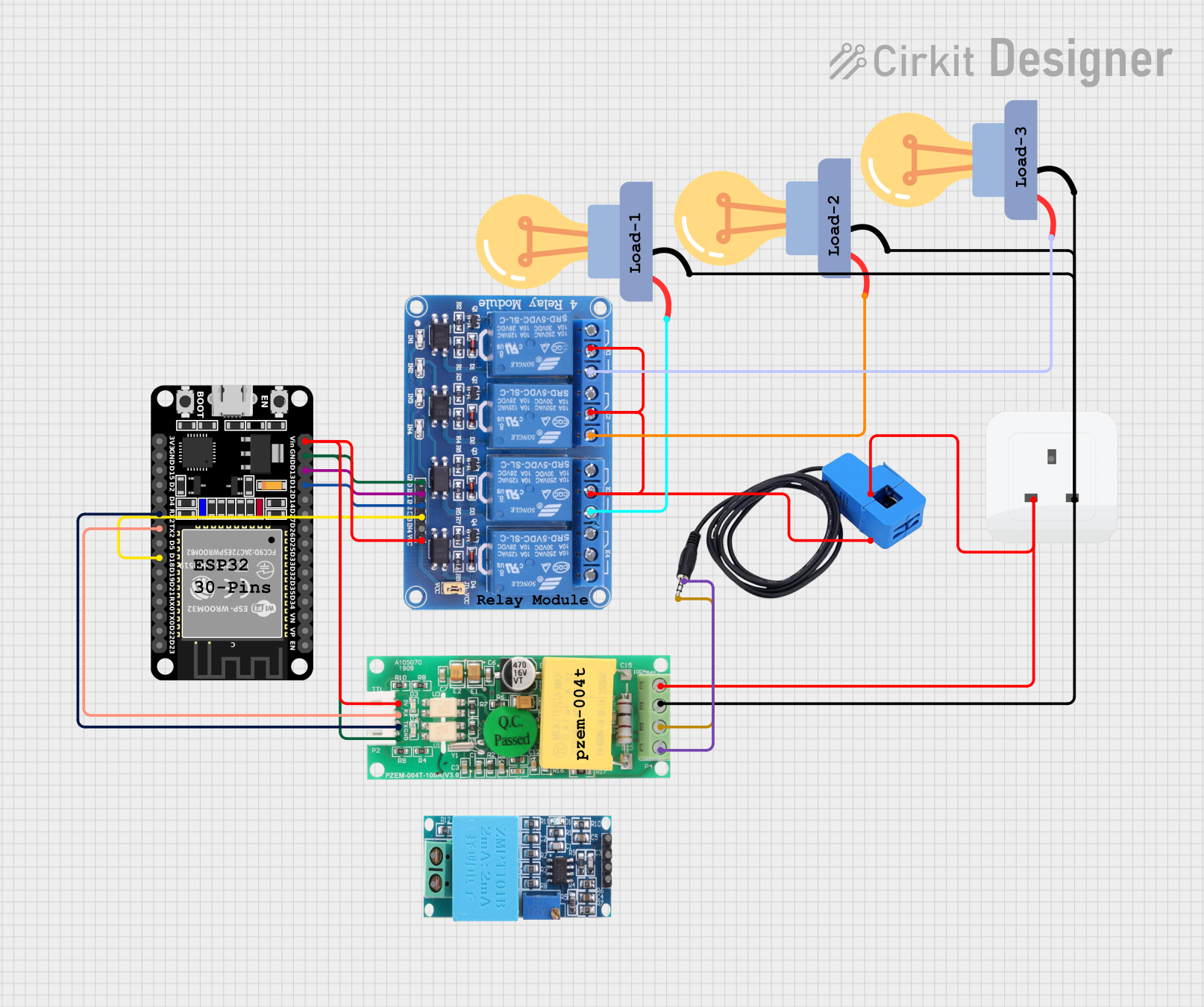
Explore Projects Built with PZEM-004T V4 (10A)
Common Applications
- Home energy monitoring systems
- Industrial equipment power usage tracking
- Renewable energy systems (e.g., solar or wind power monitoring)
- Smart IoT-based energy management solutions
Technical Specifications
Below are the key technical details of the PZEM-004T V4 (10A):
| Parameter | Specification |
|---|---|
| Voltage Range | 80V - 260V AC |
| Current Range | 0A - 10A |
| Power Range | 0W - 2.3kW |
| Energy Range | 0kWh - 9999kWh |
| Frequency Range | 45Hz - 65Hz |
| Power Factor Range | 0.00 - 1.00 |
| Communication Interface | TTL (3.3V/5V compatible) |
| Baud Rate | 9600 bps |
| Accuracy | ±0.5% |
| Operating Temperature | -10°C to 60°C |
| Dimensions | 48mm x 23mm x 15mm |
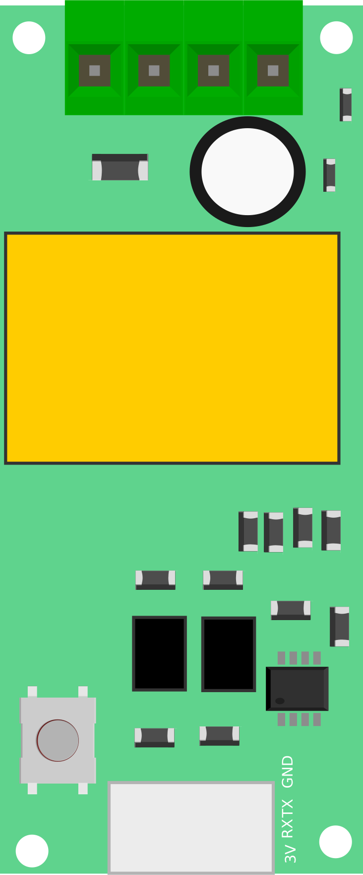
Pin Configuration
The PZEM-004T V4 module has a 4-pin interface for communication and power. Below is the pin configuration:
| Pin | Name | Description |
|---|---|---|
| 1 | VCC | Power supply input (5V DC) |
| 2 | GND | Ground connection |
| 3 | RX | UART Receive pin (connect to TX of microcontroller) |
| 4 | TX | UART Transmit pin (connect to RX of microcontroller) |
Usage Instructions
Connecting the PZEM-004T V4 to a Microcontroller
- Power Supply: Connect the
VCCpin to a 5V DC power source and theGNDpin to ground. - UART Communication: Connect the
RXpin of the module to theTXpin of the microcontroller and theTXpin of the module to theRXpin of the microcontroller. - AC Measurement: Connect the module's input terminals to the AC line and load as per the wiring diagram provided in the module's datasheet. Ensure proper insulation and safety precautions when working with high voltage.
Important Considerations
- Isolation: The module does not provide electrical isolation. Use an isolation transformer or other safety measures when working with high-voltage AC circuits.
- Current Limit: Ensure the load current does not exceed 10A to prevent damage to the module.
- Baud Rate: The default UART baud rate is 9600 bps. Ensure your microcontroller is configured to communicate at this rate.
- Library Support: For Arduino users, libraries like
PZEM004Tare available to simplify communication with the module.
Example Code for Arduino UNO
Below is an example of how to interface the PZEM-004T V4 with an Arduino UNO to read voltage, current, and power:
#include <PZEM004Tv30.h> // Include the PZEM-004T V4 library

// Define the RX and TX pins for communication
#define RX_PIN 10
#define TX_PIN 11

// Create a PZEM object with the specified RX and TX pins
PZEM004Tv30 pzem(RX_PIN, TX_PIN);

void setup() {
  Serial.begin(9600); // Initialize serial communication for debugging
  Serial.println("PZEM-004T V4 Energy Monitor");
}

void loop() {
  // Read voltage
  float voltage = pzem.voltage();
  if (!isnan(voltage)) {
    Serial.print("Voltage: ");
    Serial.print(voltage);
    Serial.println(" V");
  } else {
    Serial.println("Error reading voltage!");
  }

  // Read current
  float current = pzem.current();
  if (!isnan(current)) {
    Serial.print("Current: ");
    Serial.print(current);
    Serial.println(" A");
  } else {
    Serial.println("Error reading current!");
  }

  // Read power
  float power = pzem.power();
  if (!isnan(power)) {
    Serial.print("Power: ");
    Serial.print(power);
    Serial.println(" W");
  } else {
    Serial.println("Error reading power!");
  }

  // Add a delay to avoid flooding the serial monitor
  delay(1000);
}
Notes on the Code
- The
PZEM004Tv30library must be installed in the Arduino IDE. You can install it via the Library Manager. - Ensure the RX and TX pins defined in the code match the physical connections on your Arduino.
Troubleshooting and FAQs
Common Issues
No Data or Incorrect Readings:
- Ensure the wiring is correct, especially the RX and TX connections.
- Verify that the baud rate is set to 9600 bps in both the module and the microcontroller.
- Check that the AC input voltage and current are within the module's specified range.
Module Not Responding:
- Confirm that the module is powered with a stable 5V DC supply.
- Ensure the microcontroller's UART pins are not being used by other peripherals.
Inconsistent Readings:
- Verify that the load current does not exceed 10A.
- Check for loose connections or interference in the AC wiring.
FAQs
Q1: Can the PZEM-004T V4 measure DC voltage or current?
No, the module is designed specifically for AC voltage and current measurement.
Q2: Is the module compatible with 3.3V logic microcontrollers like ESP8266 or ESP32?
Yes, the UART interface is compatible with both 3.3V and 5V logic levels.
Q3: How can I reset the energy counter?
The energy counter can be reset using a specific command sent via the UART interface. Refer to the module's datasheet for details.
Q4: Can I use this module for loads exceeding 10A?
No, the module is rated for a maximum current of 10A. For higher loads, consider using a current transformer with a compatible energy monitoring module.
Q5: Does the module provide electrical isolation?
No, the module does not provide isolation. Use appropriate safety measures when working with high-voltage circuits.