
How to Use Peristaltic Pump: Examples, Pinouts, and Specs
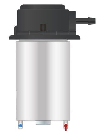
 Design with Peristaltic Pump in Cirkit Designer
Introduction
A peristaltic pump is a type of positive displacement pump designed to move fluids through a flexible tube by compressing and relaxing the tube in a sequential manner. This action creates a vacuum that draws the fluid into the tube and pushes it out. The pump is highly valued for its ability to handle viscous fluids, maintain sterile conditions, and prevent contamination since the fluid only comes into contact with the tubing.
Explore Projects Built with Peristaltic Pump
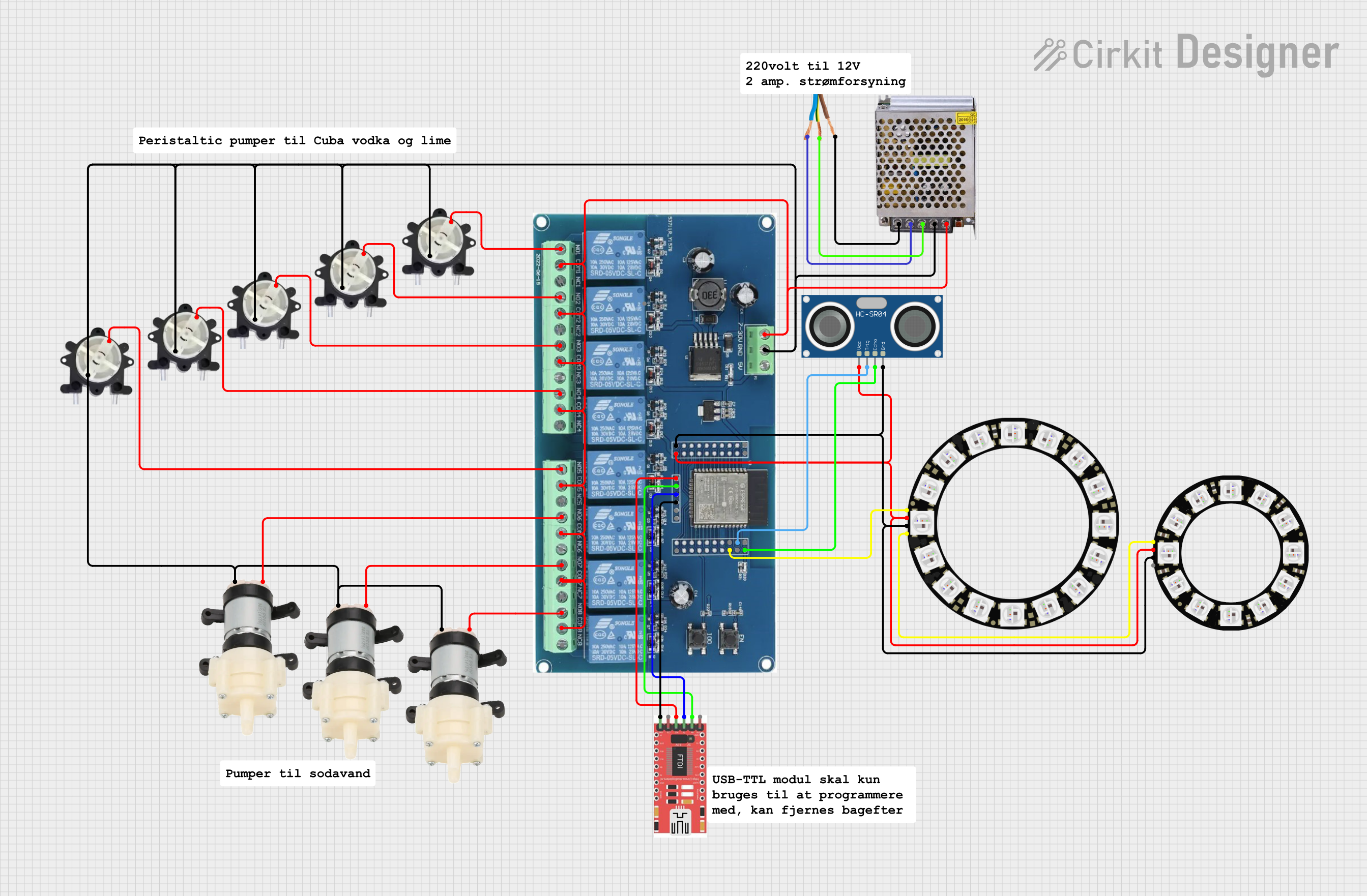 Open Project in Cirkit Designer
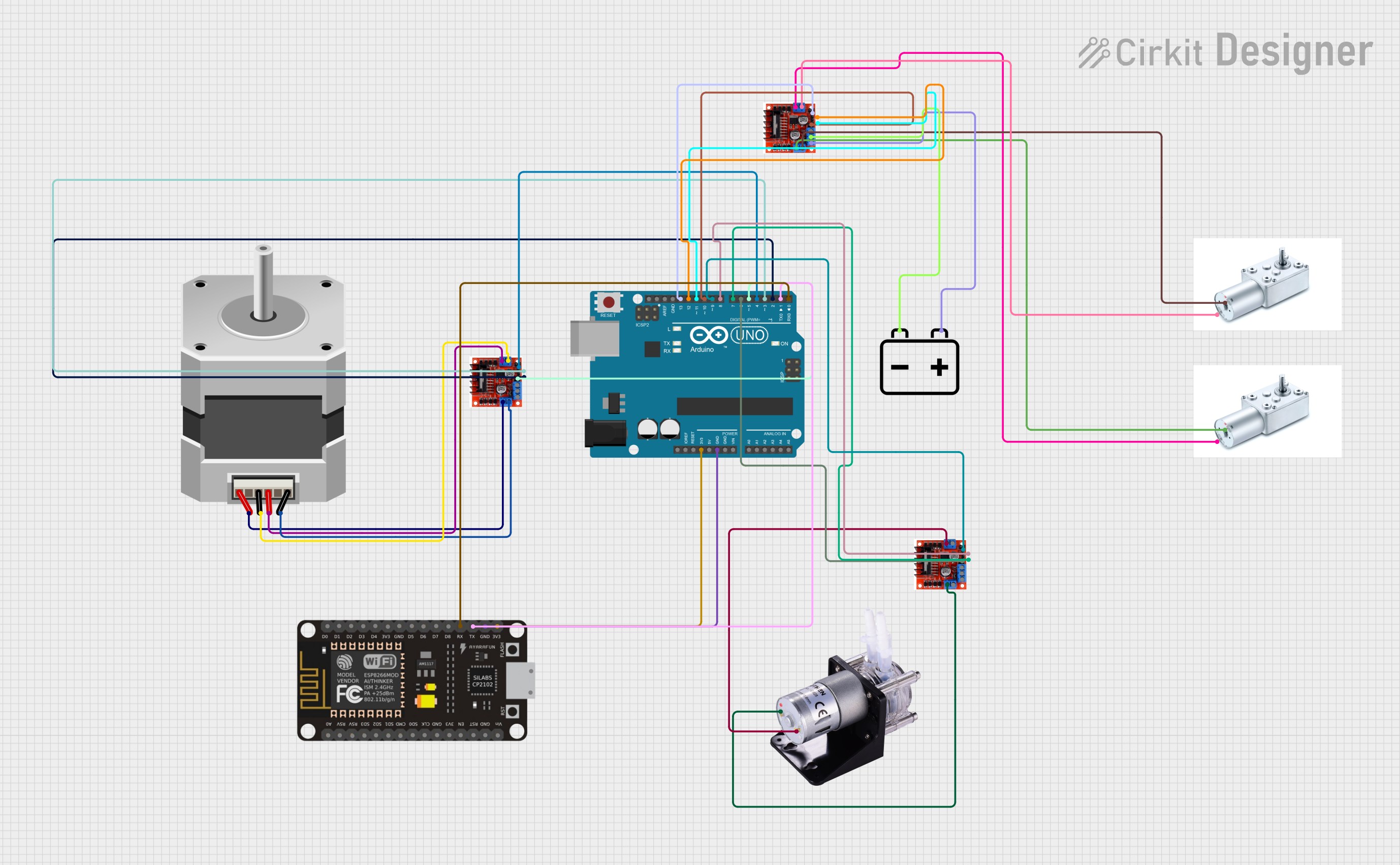 Open Project in Cirkit Designer
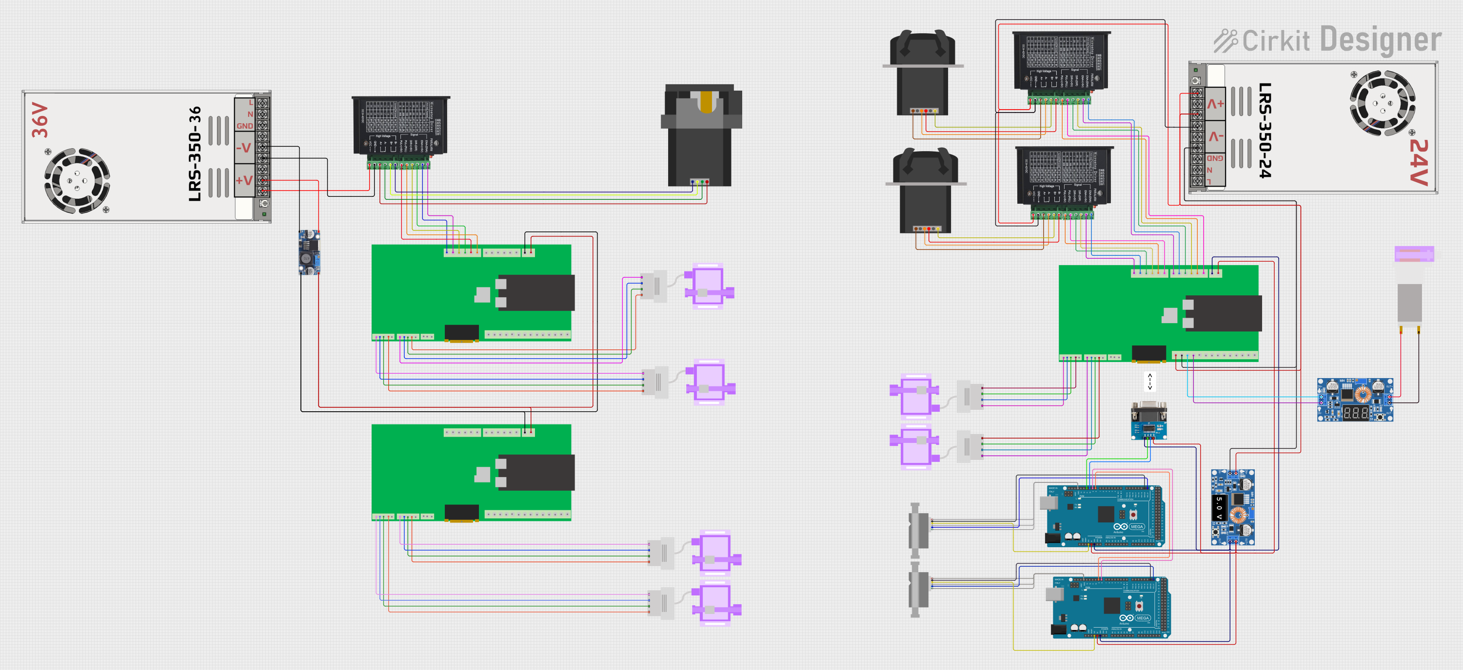 Open Project in Cirkit Designer
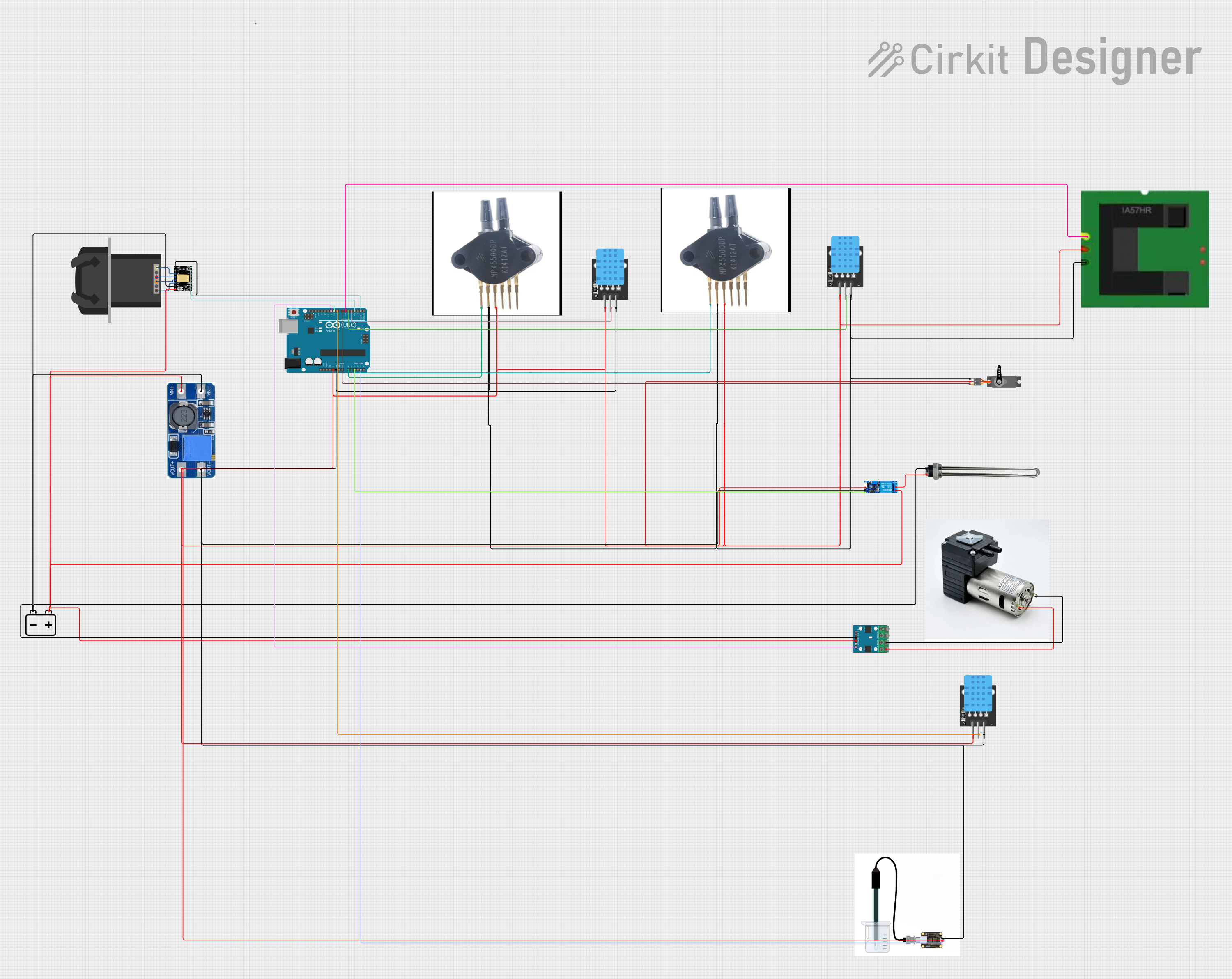 Open Project in Cirkit Designer
Explore Projects Built with Peristaltic Pump
Open Project in Cirkit DesignerOpen Project in Cirkit DesignerOpen Project in Cirkit DesignerOpen Project in Cirkit DesignerCommon Applications and Use Cases
- Medical Applications: Used in dialysis machines, infusion pumps, and blood circulation systems.
- Laboratory Settings: Ideal for transferring chemicals, biological samples, and other sensitive fluids.
- Industrial Processes: Used in food processing, water treatment, and chemical dosing systems.
- Aquarium and Hydroponics: For precise dosing of nutrients, water, or chemicals.
Technical Specifications
Below are the general technical specifications for a typical peristaltic pump. Note that specific models may vary, so always refer to the datasheet of your pump.
Key Technical Details
- Operating Voltage: 5V to 24V DC (depending on the model)
- Current Consumption: 100mA to 1A (varies with load and voltage)
- Flow Rate: 10 mL/min to 1000 mL/min (model-dependent)
- Tube Material: Silicone, PVC, or other flexible materials
- Tube Inner Diameter: 1 mm to 8 mm
- Maximum Pressure: 2 to 3 bar
- Lifespan: 1000 to 3000 hours (depending on usage and tubing material)
Pin Configuration and Descriptions
Most peristaltic pumps are simple DC motor-driven devices with two terminals. However, some advanced models may include additional control features. Below is a typical pin configuration:
| Pin | Label | Description |
|---|---|---|
| 1 | Positive (+) | Connect to the positive terminal of the power supply or motor driver. |
| 2 | Negative (-) | Connect to the negative terminal of the power supply or motor driver. |
For pumps with integrated controllers:
| Pin | Label | Description |
|---|---|---|
| 1 | VCC | Power input (e.g., 5V or 12V DC). |
| 2 | GND | Ground connection. |
| 3 | PWM/Control | Optional input for speed control using a PWM signal. |
Usage Instructions
How to Use the Component in a Circuit
- Power Supply: Ensure the pump is powered by a DC voltage within its operating range (e.g., 12V DC). Use a regulated power supply to avoid voltage spikes.
- Motor Driver (Optional): If controlling the pump with a microcontroller (e.g., Arduino), use a motor driver (e.g., L298N or ULN2003) to handle the current requirements.
- Tubing Installation: Insert the flexible tubing into the pump head, ensuring it is properly seated and not kinked.
- Fluid Handling: Connect the inlet and outlet ends of the tubing to the desired fluid source and destination.
- Control: For pumps with PWM control, connect the control pin to a PWM-capable pin on your microcontroller.
Important Considerations and Best Practices
- Tubing Material: Use tubing compatible with the fluid being pumped to avoid degradation or contamination.
- Flow Direction: The pump's flow direction can be reversed by swapping the polarity of the power connections.
- Avoid Dry Running: Running the pump without fluid can damage the tubing and reduce its lifespan.
- Speed Control: Use PWM signals to adjust the pump speed for precise flow rate control.
- Maintenance: Regularly inspect and replace the tubing to maintain performance and prevent leaks.
Example: Controlling a Peristaltic Pump with Arduino UNO
Below is an example of how to control a peristaltic pump using an Arduino UNO and an L298N motor driver.
// Define motor driver pins
const int IN1 = 9;  // Motor driver input 1
const int IN2 = 10; // Motor driver input 2
const int ENA = 11; // Motor driver enable pin (PWM)

// Setup function
void setup() {
  pinMode(IN1, OUTPUT); // Set IN1 as output
  pinMode(IN2, OUTPUT); // Set IN2 as output
  pinMode(ENA, OUTPUT); // Set ENA as output
}

// Loop function
void loop() {
  // Rotate pump in forward direction
  digitalWrite(IN1, HIGH); // Set IN1 high
  digitalWrite(IN2, LOW);  // Set IN2 low
  analogWrite(ENA, 128);   // Set speed to 50% (PWM value: 0-255)

  delay(5000); // Run pump for 5 seconds

  // Stop the pump
  analogWrite(ENA, 0); // Set speed to 0
  delay(2000);         // Wait for 2 seconds

  // Rotate pump in reverse direction
  digitalWrite(IN1, LOW);  // Set IN1 low
  digitalWrite(IN2, HIGH); // Set IN2 high
  analogWrite(ENA, 128);   // Set speed to 50%

  delay(5000); // Run pump for 5 seconds

  // Stop the pump
  analogWrite(ENA, 0); // Set speed to 0
  delay(2000);         // Wait for 2 seconds
}
Troubleshooting and FAQs
Common Issues and Solutions
Pump Not Running
- Cause: Incorrect power supply or loose connections.
- Solution: Verify the power supply voltage and current. Check all connections.
Low Flow Rate
- Cause: Tubing is kinked, worn out, or too small for the application.
- Solution: Inspect and replace the tubing. Use tubing with a larger inner diameter if needed.
Pump Overheating
- Cause: Prolonged operation at high speeds or excessive load.
- Solution: Reduce the operating speed or allow the pump to cool periodically.
Fluid Leakage
- Cause: Damaged or improperly installed tubing.
- Solution: Replace the tubing and ensure it is properly seated in the pump head.
FAQs
Can I use the pump for corrosive fluids?
- Yes, but ensure the tubing material is compatible with the fluid to prevent damage.
How do I reverse the flow direction?
- Swap the polarity of the power connections to the pump.
What is the lifespan of the tubing?
- Tubing lifespan depends on the material and usage but typically ranges from 1000 to 3000 hours.
Can I control the pump speed without a microcontroller?
- Yes, you can use a variable DC power supply or a manual PWM controller to adjust the speed.