How to Use RP Lidar A1M8 (old): Examples, Pinouts, and Specs
Introduction
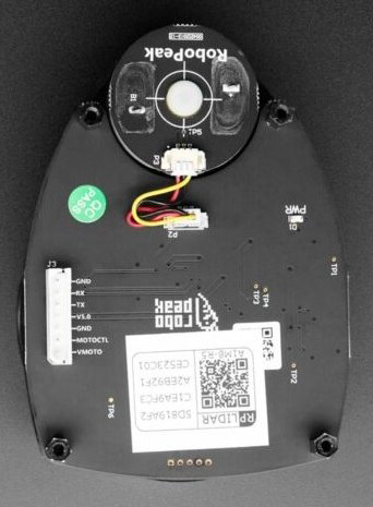
The RP Lidar A1M8, manufactured by Slamtec, is a 360-degree laser scanner designed for mapping and navigation applications. It uses laser triangulation to provide accurate distance measurements in real-time, making it an essential component for robotics, autonomous vehicles, and other systems requiring obstacle detection and environmental mapping. Its compact design, low power consumption, and high scanning frequency make it a popular choice for developers and engineers.
Explore Projects Built with RP Lidar A1M8 (old)
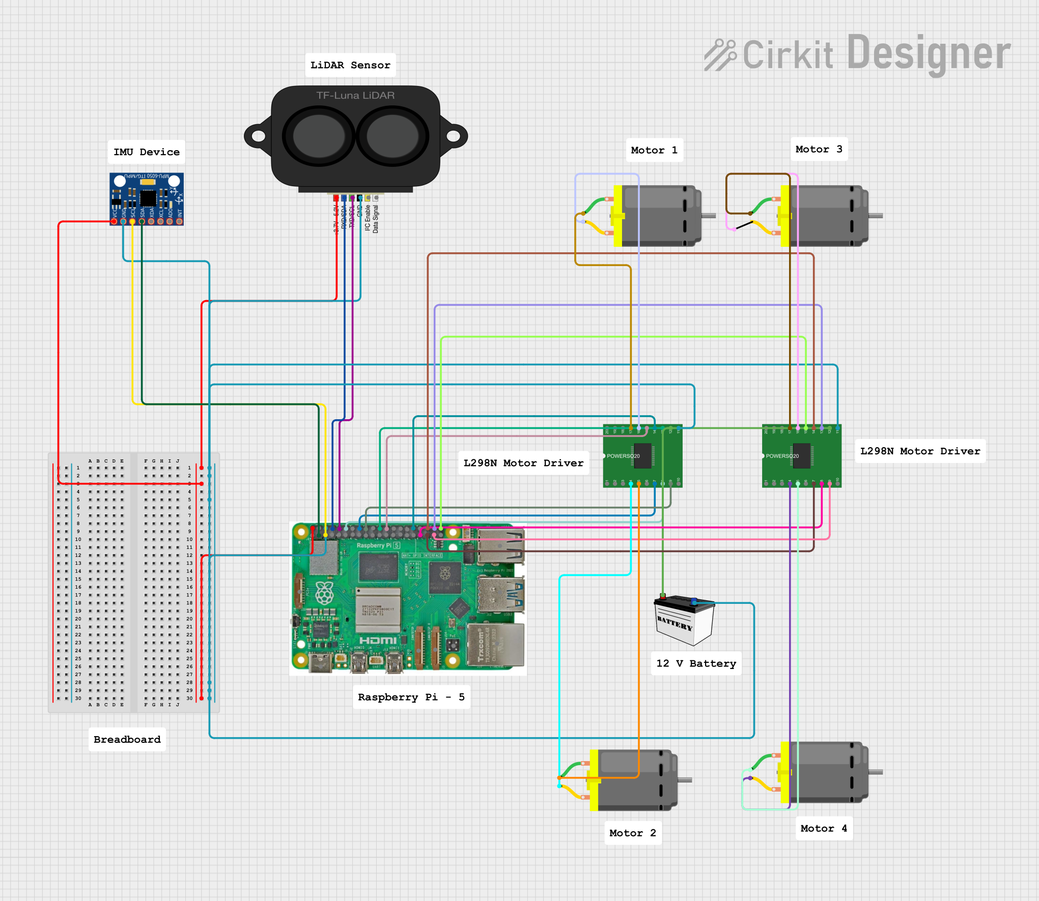
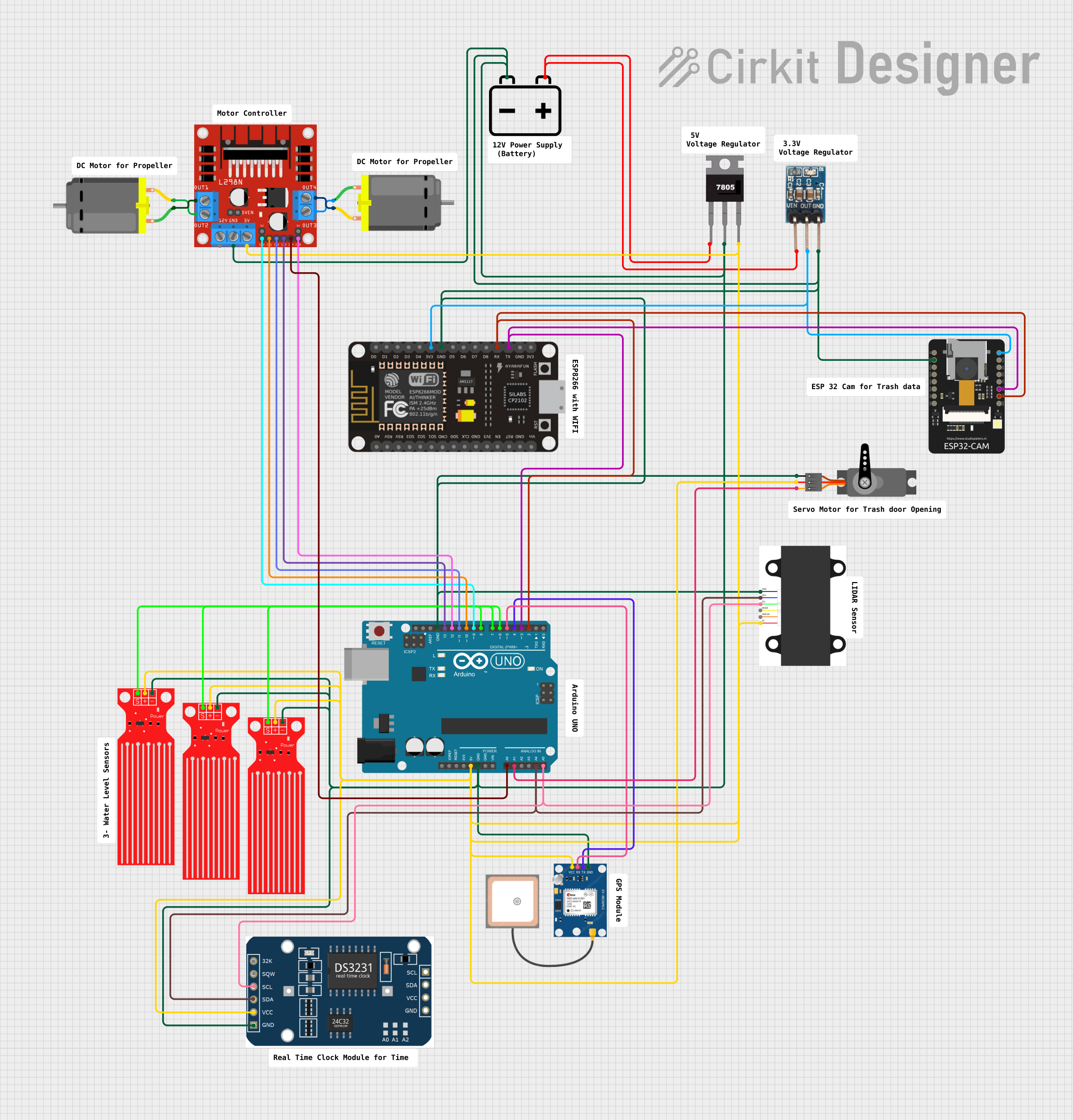

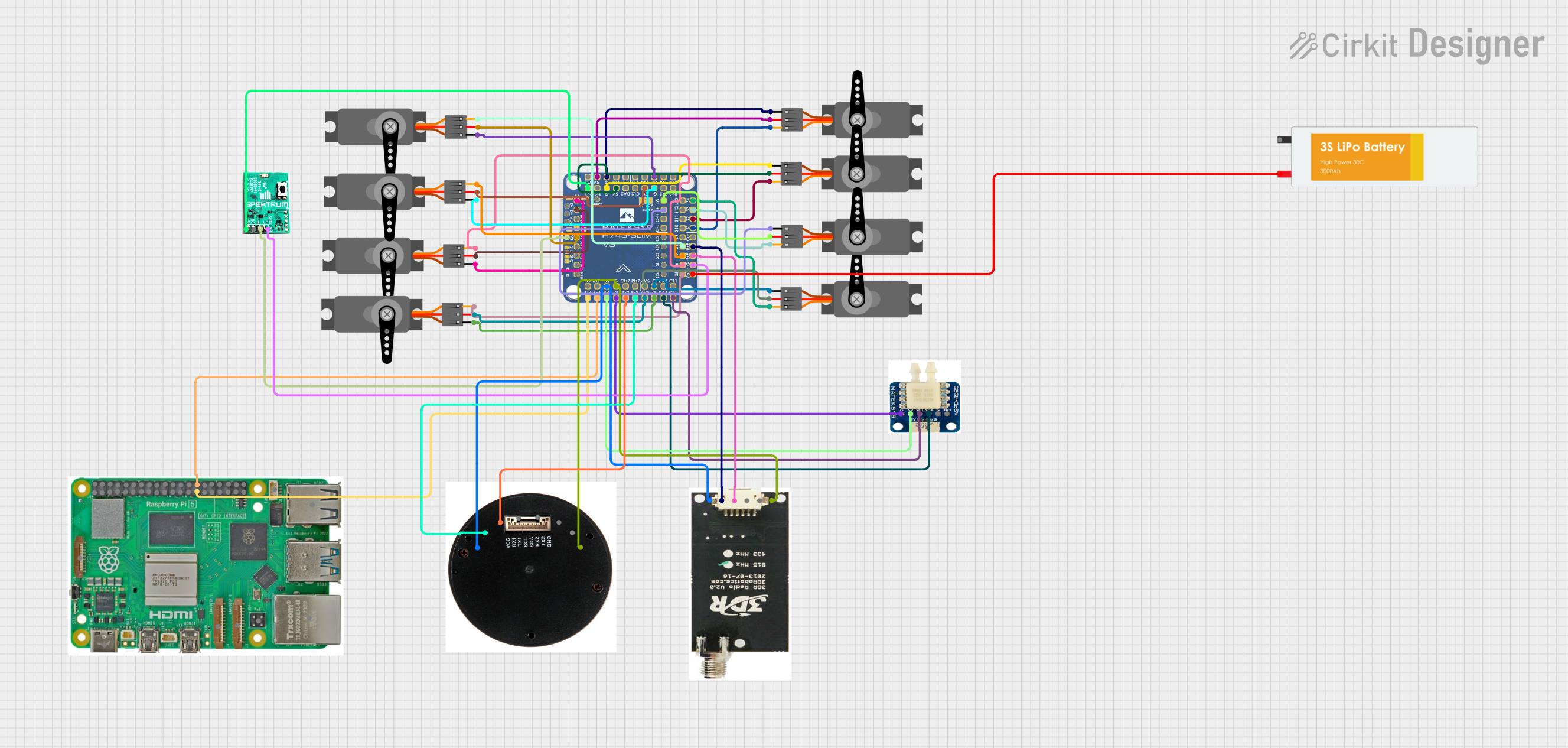
Explore Projects Built with RP Lidar A1M8 (old)
Common Applications
- Robotics navigation and obstacle avoidance
- Autonomous vehicle mapping
- SLAM (Simultaneous Localization and Mapping) systems
- Indoor and outdoor environment scanning
- Industrial automation and safety systems
Technical Specifications
The RP Lidar A1M8 is a versatile and reliable sensor with the following key specifications:
| Parameter | Value |
|---|---|
| Scanning Range | 0.15 m to 12 m |
| Scanning Angle | 360° |
| Angular Resolution | 1° to 1.5° |
| Distance Resolution | < 1% of the actual distance |
| Scanning Frequency | 5 Hz to 10 Hz |
| Laser Wavelength | 785 nm (Infrared) |
| Laser Safety | Class 1 (Eye-safe) |
| Operating Voltage | 5 V DC |
| Power Consumption | 2.5 W (typical) |
| Communication Interface | UART (3.3V TTL) |
| Dimensions | 70 mm (diameter) x 41 mm (height) |
| Weight | 190 g |
Pin Configuration
The RP Lidar A1M8 uses a 4-pin connector for power and communication. The pinout is as follows:
| Pin | Name | Description |
|---|---|---|
| 1 | VCC | Power input (5 V DC) |
| 2 | GND | Ground |
| 3 | TX | UART Transmit (3.3V TTL) |
| 4 | RX | UART Receive (3.3V TTL) |
Usage Instructions
Connecting the RP Lidar A1M8
- Power Supply: Connect the VCC pin to a 5V DC power source and the GND pin to ground.
- Communication: Use the TX and RX pins to establish a UART connection with your microcontroller or computer. Ensure the UART voltage level is 3.3V TTL.
- Mounting: Secure the lidar on a stable platform to minimize vibrations during operation. The lidar should have an unobstructed 360° view for optimal performance.
Using with Arduino UNO
To use the RP Lidar A1M8 with an Arduino UNO, you will need a USB-to-TTL adapter or a hardware UART interface. Below is an example code snippet to interface the lidar with Arduino:
#include <SoftwareSerial.h>

// Define RX and TX pins for SoftwareSerial
SoftwareSerial lidarSerial(10, 11); // RX = pin 10, TX = pin 11

void setup() {
  Serial.begin(9600); // Initialize Serial Monitor
  lidarSerial.begin(115200); // Initialize Lidar UART communication

  Serial.println("RP Lidar A1M8 Initialized");
}

void loop() {
  if (lidarSerial.available()) {
    // Read data from the lidar
    byte data = lidarSerial.read();
    Serial.print("Lidar Data: ");
    Serial.println(data, HEX); // Print data in hexadecimal format
  }
}
Important Considerations
- Power Supply: Ensure a stable 5V power source to avoid performance issues.
- UART Voltage: The RP Lidar A1M8 operates at 3.3V TTL levels. Use a level shifter if your microcontroller operates at 5V.
- Environment: Avoid direct sunlight or reflective surfaces, as they may interfere with the laser measurements.
- Firmware: Check for firmware updates from Slamtec to ensure optimal performance.
Troubleshooting and FAQs
Common Issues
No Data Output:
- Ensure the lidar is powered correctly (5V on VCC and proper ground connection).
- Verify the UART connection and baud rate (default is 115200 bps).
- Check for loose or damaged wires.
Inaccurate Measurements:
- Ensure the lidar has a clear 360° view without obstructions.
- Avoid using the lidar in environments with excessive dust or reflective surfaces.
Lidar Not Spinning:
- Check the motor control signal and ensure the motor is not obstructed.
- Verify the power supply is sufficient to drive the motor.
FAQs
Q: Can the RP Lidar A1M8 be used outdoors?
A: Yes, but it performs best in controlled environments. Direct sunlight or heavy rain may affect its accuracy.
Q: What is the maximum range of the lidar?
A: The maximum range is 12 meters under optimal conditions.
Q: Is the laser safe for human eyes?
A: Yes, the RP Lidar A1M8 uses a Class 1 laser, which is eye-safe.
Q: Can I increase the scanning frequency?
A: Yes, the scanning frequency can be adjusted between 5 Hz and 10 Hz, but higher frequencies may reduce the angular resolution.
By following this documentation, you can effectively integrate and troubleshoot the RP Lidar A1M8 in your projects.