
How to Use PNP-Transistor: Examples, Pinouts, and Specs

 Design with PNP-Transistor in Cirkit Designer
Introduction
A PNP transistor is a type of bipolar junction transistor (BJT) that allows current to flow from the emitter to the collector when a small current is applied to the base. Unlike its counterpart, the NPN transistor, the PNP transistor is activated when the base is pulled to a lower voltage than the emitter. This component is widely used in electronic circuits for switching and amplification purposes.
Explore Projects Built with PNP-Transistor
 Open Project in Cirkit Designer
 Open Project in Cirkit Designer
 Open Project in Cirkit Designer
 Open Project in Cirkit Designer
Explore Projects Built with PNP-Transistor
Open Project in Cirkit DesignerOpen Project in Cirkit DesignerOpen Project in Cirkit DesignerOpen Project in Cirkit DesignerCommon Applications and Use Cases
- Switching Circuits: Used to control high-current loads with a low-current signal.
- Amplifiers: Enhances weak signals in audio, radio, and other electronic systems.
- Current Sources: Provides a stable current in various circuit designs.
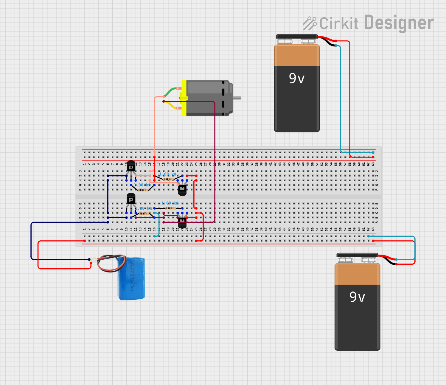
- H-Bridge Motor Drivers: Used in conjunction with NPN transistors for bidirectional motor control.
Technical Specifications
Below are the general technical specifications for a typical PNP transistor. Note that specific values may vary depending on the model (e.g., 2N2907, BC557).
| Parameter | Typical Value |
|---|---|
| Maximum Collector-Emitter Voltage (VCEO) | 40V to 60V |
| Maximum Collector Current (IC) | 100mA to 800mA |
| Maximum Power Dissipation (PD) | 500mW to 1W |
| DC Current Gain (hFE) | 100 to 300 |
| Transition Frequency (fT) | 100MHz to 300MHz |
| Operating Temperature Range | -55°C to +150°C |
Pin Configuration and Descriptions
The PNP transistor typically has three pins: Emitter (E), Base (B), and Collector (C). The pinout may vary depending on the package type (e.g., TO-92, TO-220). Below is a table for the TO-92 package, which is common for small-signal PNP transistors.
| Pin Number | Pin Name | Description |
|---|---|---|
| 1 | Emitter (E) | Current flows out of this pin to the external circuit. |
| 2 | Base (B) | Controls the transistor's operation by receiving a small current. |
| 3 | Collector (C) | Current flows into this pin from the external circuit. |
Usage Instructions
How to Use the PNP Transistor in a Circuit
- Biasing the Transistor:
- To turn the PNP transistor ON, the base voltage must be lower than the emitter voltage (typically by 0.6V to 0.7V for silicon transistors).
- To turn the transistor OFF, the base voltage should be equal to or higher than the emitter voltage.
- Connecting the Load:
- The load (e.g., a motor or LED) is typically connected between the collector and the positive supply voltage.
- Ensure the load's current does not exceed the transistor's maximum collector current rating.
- Base Resistor:
- Use a resistor between the base and the control signal to limit the base current. The resistor value can be calculated using Ohm's law:
[ R_B = \frac{V_{control} - V_{BE}}{I_B} ] where ( V_{control} ) is the control signal voltage, ( V_{BE} ) is the base-emitter voltage (typically 0.6V), and ( I_B ) is the required base current.
- Use a resistor between the base and the control signal to limit the base current. The resistor value can be calculated using Ohm's law:
Example Circuit with Arduino UNO
Below is an example of using a PNP transistor to control an LED with an Arduino UNO.
Circuit Description:
- The emitter is connected to the 5V supply.
- The collector is connected to one terminal of the LED, with the other terminal connected to a resistor and then to ground.
- The base is connected to an Arduino digital pin through a 10kΩ resistor.
Arduino Code:
// Define the pin connected to the PNP transistor's base
const int transistorBasePin = 9;

void setup() {
  pinMode(transistorBasePin, OUTPUT); // Set the pin as an output
}

void loop() {
  digitalWrite(transistorBasePin, LOW);
  // Set base to LOW to turn the transistor ON and light up the LED
  delay(1000); // Wait for 1 second

  digitalWrite(transistorBasePin, HIGH);
  // Set base to HIGH to turn the transistor OFF and turn off the LED
  delay(1000); // Wait for 1 second
}
Important Considerations and Best Practices
- Polarity: Ensure correct polarity when connecting the transistor. Reversing the emitter and collector can damage the component.
- Heat Dissipation: For high-power applications, use a heat sink to prevent overheating.
- Saturation Mode: To fully turn on the transistor, ensure the base current is sufficient to drive the transistor into saturation.
- Avoid Exceeding Ratings: Do not exceed the maximum voltage, current, or power ratings specified in the datasheet.
Troubleshooting and FAQs
Common Issues
- Transistor Not Turning On:
- Check if the base voltage is sufficiently lower than the emitter voltage.
- Verify the base resistor value to ensure adequate base current.
- Excessive Heat:
- Ensure the load current does not exceed the transistor's maximum collector current rating.
- Use a heat sink if necessary.
- No Current Flow Through the Load:
- Verify the connections and ensure the load is properly connected between the collector and the positive supply.
- Check for a damaged transistor by testing it with a multimeter.
FAQs
Q1: Can I use a PNP transistor in place of an NPN transistor?
A1: No, PNP and NPN transistors have opposite polarities and require different biasing. However, they can be used together in complementary configurations.
Q2: How do I test if a PNP transistor is working?
A2: Use a multimeter in diode mode:
- Place the positive probe on the emitter and the negative probe on the base. You should see a forward voltage drop (~0.6V for silicon transistors).
- Reverse the probes; there should be no conduction.
- Repeat the test between the collector and base.
Q3: What happens if I exceed the maximum ratings?
A3: Exceeding voltage, current, or power ratings can permanently damage the transistor or cause it to fail.
By following this documentation, you can effectively use a PNP transistor in your electronic projects!