
How to Use Pi2w back: Examples, Pinouts, and Specs
 Design with Pi2w back in Cirkit Designer
Introduction
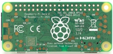
The Pi2w Back is a custom-designed back cover specifically tailored for Raspberry Pi 2 and 3 models. It provides robust protection for the Raspberry Pi's circuitry while maintaining access to the GPIO (General Purpose Input/Output) pins. This makes it an ideal solution for users who want to integrate their Raspberry Pi into various projects without compromising on safety or functionality. Additionally, the Pi2w Back is designed for easy mounting, making it suitable for both prototyping and permanent installations.
Explore Projects Built with Pi2w back
 Open Project in Cirkit Designer
 Open Project in Cirkit Designer
 Open Project in Cirkit Designer
 Open Project in Cirkit Designer
Explore Projects Built with Pi2w back
Open Project in Cirkit DesignerOpen Project in Cirkit DesignerOpen Project in Cirkit DesignerOpen Project in Cirkit DesignerCommon Applications and Use Cases
- Protecting Raspberry Pi boards in DIY electronics projects.
- Providing access to GPIO pins for sensor and peripheral connections.
- Mounting Raspberry Pi boards in enclosures or on surfaces for industrial or home automation projects.
- Enhancing the durability of Raspberry Pi setups in educational environments.
Technical Specifications
The Pi2w Back is a passive mechanical component, but its design includes features that enhance usability and compatibility with Raspberry Pi 2 and 3 models.
Key Features
- Material: Durable ABS plastic.
- Compatibility: Raspberry Pi 2 Model B and Raspberry Pi 3 Model B.
- GPIO Access: Cutouts for 40-pin GPIO header.
- Mounting Options: Pre-drilled holes for screws or standoffs.
- Dimensions: Matches the Raspberry Pi 2/3 form factor (85.6mm x 56.5mm).
- Weight: Approximately 20 grams.
GPIO Pin Access
The Pi2w Back includes a cutout for the 40-pin GPIO header, allowing users to connect peripherals without removing the cover. Below is a reference table for the GPIO pinout of Raspberry Pi 2/3 models:
| Pin Number | Pin Name | Description |
|---|---|---|
| 1 | 3.3V Power | Power supply (3.3V) |
| 2 | 5V Power | Power supply (5V) |
| 3 | GPIO2 (SDA1) | I2C Data Line |
| 4 | 5V Power | Power supply (5V) |
| 5 | GPIO3 (SCL1) | I2C Clock Line |
| 6 | Ground | Ground |
| ... | ... | ... (Refer to full GPIO pinout) |
For the complete GPIO pinout, refer to the Raspberry Pi documentation.
Usage Instructions
Installing the Pi2w Back
- Prepare the Raspberry Pi: Ensure the Raspberry Pi 2 or 3 is powered off and disconnected from any power source.
- Align the Pi2w Back: Place the Pi2w Back over the Raspberry Pi, ensuring the GPIO cutout aligns with the 40-pin header.
- Secure the Cover: Use screws or standoffs to attach the Pi2w Back to the Raspberry Pi. Ensure all mounting points are properly secured.
- Connect Peripherals: Attach any required peripherals to the GPIO pins or other ports as needed.
Important Considerations
- Ventilation: The Pi2w Back does not include active cooling. If your project generates significant heat, consider adding a heatsink or external fan.
- GPIO Clearance: Ensure that any connected GPIO cables or hats (Hardware Attached on Top) fit within the cutout area.
- Static Precautions: Handle the Raspberry Pi and Pi2w Back with care to avoid static discharge, which can damage electronic components.
Example: Using the Pi2w Back with an Arduino UNO
The Pi2w Back allows easy access to GPIO pins, enabling integration with external microcontrollers like the Arduino UNO. Below is an example of connecting an LED to the Raspberry Pi GPIO pin and controlling it via Python:
Import the GPIO library for Raspberry Pi
import RPi.GPIO as GPIO import time
Set up GPIO mode and pin
GPIO.setmode(GPIO.BCM) # Use Broadcom pin numbering LED_PIN = 18 # GPIO pin connected to the LED GPIO.setup(LED_PIN, GPIO.OUT) # Set the pin as an output
try: while True: GPIO.output(LED_PIN, GPIO.HIGH) # Turn on the LED time.sleep(1) # Wait for 1 second GPIO.output(LED_PIN, GPIO.LOW) # Turn off the LED time.sleep(1) # Wait for 1 second except KeyboardInterrupt: # Clean up GPIO settings when exiting GPIO.cleanup()
Notes:
- Ensure the LED is connected to the correct GPIO pin with a current-limiting resistor (e.g., 330Ω).
- The Pi2w Back provides sufficient clearance for GPIO connections.
Troubleshooting and FAQs
Common Issues
The Pi2w Back does not fit properly.
- Ensure you are using a Raspberry Pi 2 or 3 model. The Pi2w Back is not compatible with other Raspberry Pi models.
- Check for any obstructions or improperly aligned components.
GPIO connections are difficult to access.
- Verify that the GPIO cutout is aligned with the 40-pin header.
- Use angled GPIO connectors or ribbon cables for easier access.
Overheating issues.
- The Pi2w Back does not include ventilation for active cooling. If overheating occurs, consider adding external cooling solutions like a fan or heatsink.
FAQs
Can I use the Pi2w Back with a Raspberry Pi 4? No, the Pi2w Back is designed specifically for Raspberry Pi 2 and 3 models. The Raspberry Pi 4 has a different form factor and port layout.
Does the Pi2w Back include screws or mounting hardware? No, screws or standoffs must be purchased separately.
Can I use HATs with the Pi2w Back installed? Yes, as long as the HAT fits within the GPIO cutout area and does not interfere with the cover.
Is the Pi2w Back available in different colors? The Pi2w Back is typically available in black, but other colors may be available depending on the manufacturer or retailer.
By following this documentation, you can effectively use the Pi2w Back to protect and enhance your Raspberry Pi projects.