Cirkit Designer Logo
Cirkit Designer
Your all-in-one circuit design IDE
Home / 
Component Documentation

How to Use LR7843 Module: Examples, Pinouts, and Specs

Image of LR7843 Module
Cirkit Designer LogoDesign with LR7843 Module in Cirkit Designer

Introduction

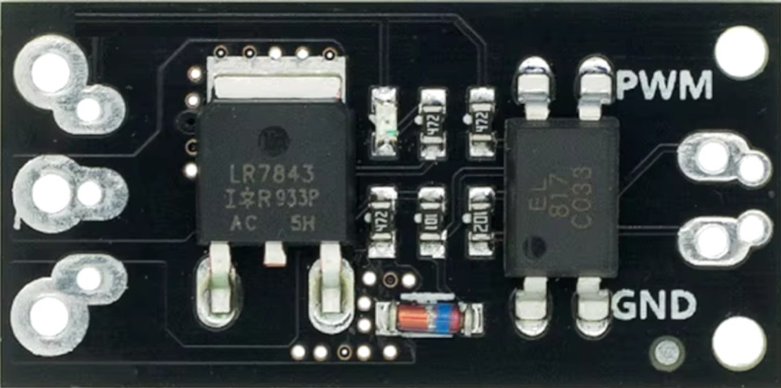
The LR7843 Module is a high-efficiency, low-dropout linear regulator designed for applications requiring low noise and precise voltage regulation. It is commonly used in power management circuits for sensitive electronic devices. This module ensures stable voltage output, making it ideal for use in audio equipment, RF applications, and other sensitive electronic devices.

Explore Projects Built with LR7843 Module

Use Cirkit Designer to design, explore, and prototype these projects online. Some projects support real-time simulation. Click "Open Project" to start designing instantly!
Cellular-Enabled IoT Device with Real-Time Clock and Power Management
Image of LRCM PHASE 2 BASIC: A project utilizing LR7843 Module in a practical application
This circuit features a LilyGo-SIM7000G module for cellular communication and GPS functionality, interfaced with an RTC DS3231 for real-time clock capabilities. It includes voltage sensing through two voltage sensor modules, and uses an 8-channel opto-coupler for isolating different parts of the circuit. Power management is handled by a buck converter connected to a DC power source and batteries, with a fuse for protection and a rocker switch for on/off control. Additionally, there's an LED for indication purposes.
Cirkit Designer LogoOpen Project in Cirkit Designer
ESP32-Based Smart Access Control System with RFID, LCD Display, and Thermal Printer
Image of SCHEMATIC: A project utilizing LR7843 Module in a practical application
This circuit is an ESP32-based system that integrates multiple peripherals including an RFID reader, a relay module, a thermal printer, an I2C LCD screen, and a micro SD card module. The ESP32 controls the relay, reads RFID tags, prints data, displays information on the LCD, and logs data to the SD card, making it suitable for applications like access control or data logging systems.
Cirkit Designer LogoOpen Project in Cirkit Designer
NFC-Enabled Access Control System with Time Logging
Image of doorlock: A project utilizing LR7843 Module in a practical application
This circuit is designed for access control with time tracking capabilities. It features an NFC/RFID reader for authentication, an RTC module (DS3231) for real-time clock functionality, and an OLED display for user interaction. A 12V relay controls a magnetic lock, which is activated upon successful NFC/RFID authentication, and a button switch is likely used for manual operation or input. The T8_S3 microcontroller serves as the central processing unit, interfacing with the NFC/RFID reader, RTC, OLED, and relay to manage the access control logic.
Cirkit Designer LogoOpen Project in Cirkit Designer
Dual-Mode LoRa and GSM Communication Device with ESP32
Image of modul gateway: A project utilizing LR7843 Module in a practical application
This circuit features an ESP32 Devkit V1 microcontroller interfaced with an RFM95 LoRa transceiver module for long-range communication and a SIM800L GSM module for cellular connectivity. Two LM2596 step-down modules are used to regulate the 12V battery voltage down to 3.3V required by the ESP32, RFM95, and SIM800L. The ESP32 facilitates data exchange between the RFM95 and SIM800L, enabling the system to send/receive data over both LoRa and GSM networks.
Cirkit Designer LogoOpen Project in Cirkit Designer

Explore Projects Built with LR7843 Module

Use Cirkit Designer to design, explore, and prototype these projects online. Some projects support real-time simulation. Click "Open Project" to start designing instantly!
Image of LRCM PHASE 2 BASIC: A project utilizing LR7843 Module in a practical application
Cellular-Enabled IoT Device with Real-Time Clock and Power Management
This circuit features a LilyGo-SIM7000G module for cellular communication and GPS functionality, interfaced with an RTC DS3231 for real-time clock capabilities. It includes voltage sensing through two voltage sensor modules, and uses an 8-channel opto-coupler for isolating different parts of the circuit. Power management is handled by a buck converter connected to a DC power source and batteries, with a fuse for protection and a rocker switch for on/off control. Additionally, there's an LED for indication purposes.
Cirkit Designer LogoOpen Project in Cirkit Designer
Image of SCHEMATIC: A project utilizing LR7843 Module in a practical application
ESP32-Based Smart Access Control System with RFID, LCD Display, and Thermal Printer
This circuit is an ESP32-based system that integrates multiple peripherals including an RFID reader, a relay module, a thermal printer, an I2C LCD screen, and a micro SD card module. The ESP32 controls the relay, reads RFID tags, prints data, displays information on the LCD, and logs data to the SD card, making it suitable for applications like access control or data logging systems.
Cirkit Designer LogoOpen Project in Cirkit Designer
Image of doorlock: A project utilizing LR7843 Module in a practical application
NFC-Enabled Access Control System with Time Logging
This circuit is designed for access control with time tracking capabilities. It features an NFC/RFID reader for authentication, an RTC module (DS3231) for real-time clock functionality, and an OLED display for user interaction. A 12V relay controls a magnetic lock, which is activated upon successful NFC/RFID authentication, and a button switch is likely used for manual operation or input. The T8_S3 microcontroller serves as the central processing unit, interfacing with the NFC/RFID reader, RTC, OLED, and relay to manage the access control logic.
Cirkit Designer LogoOpen Project in Cirkit Designer
Image of modul gateway: A project utilizing LR7843 Module in a practical application
Dual-Mode LoRa and GSM Communication Device with ESP32
This circuit features an ESP32 Devkit V1 microcontroller interfaced with an RFM95 LoRa transceiver module for long-range communication and a SIM800L GSM module for cellular connectivity. Two LM2596 step-down modules are used to regulate the 12V battery voltage down to 3.3V required by the ESP32, RFM95, and SIM800L. The ESP32 facilitates data exchange between the RFM95 and SIM800L, enabling the system to send/receive data over both LoRa and GSM networks.
Cirkit Designer LogoOpen Project in Cirkit Designer

Technical Specifications

Key Technical Details

Parameter Value
Input Voltage 2.5V to 6V
Output Voltage 1.2V to 5V (adjustable)
Output Current Up to 1.5A
Dropout Voltage 0.3V at 1A
Quiescent Current 50µA
Output Noise 40µV RMS (10Hz to 100kHz)
Operating Temp. -40°C to +125°C
Package Type SOT-223, TO-252

Pin Configuration and Descriptions

SOT-223 Package

Pin Number Pin Name Description
1 VIN Input Voltage
2 GND Ground
3 VOUT Output Voltage
4 ADJ Adjust (for setting output voltage)

TO-252 Package

Pin Number Pin Name Description
1 VIN Input Voltage
2 GND Ground
3 VOUT Output Voltage
4 ADJ Adjust (for setting output voltage)

Usage Instructions

How to Use the LR7843 Module in a Circuit

  1. Power Supply Connection:

    • Connect the input voltage (2.5V to 6V) to the VIN pin.
    • Connect the ground (GND) to the GND pin.
  2. Output Voltage Configuration:

    • Connect the VOUT pin to the load where the regulated voltage is required.
    • Use a resistor divider network between the VOUT and ADJ pins to set the desired output voltage. The output voltage can be calculated using the formula: [ V_{OUT} = V_{REF} \left(1 + \frac{R1}{R2}\right) + I_{ADJ} \times R1 ] where ( V_{REF} ) is typically 1.25V, ( R1 ) and ( R2 ) are the resistors in the divider network, and ( I_{ADJ} ) is the adjust pin current (usually negligible).
  3. Capacitor Selection:

    • Place a capacitor (typically 10µF) between the VIN and GND pins to stabilize the input voltage.
    • Place a capacitor (typically 10µF) between the VOUT and GND pins to stabilize the output voltage.

Important Considerations and Best Practices

  • Thermal Management: Ensure proper heat dissipation by using a heatsink or adequate PCB layout to avoid overheating.
  • Noise Reduction: Use low ESR capacitors to minimize output noise.
  • Load Regulation: Ensure the load current does not exceed the maximum output current rating of 1.5A.
  • PCB Layout: Keep the input and output capacitors as close to the module as possible to minimize noise and improve stability.

Troubleshooting and FAQs

Common Issues and Solutions

  1. No Output Voltage:

    • Check Connections: Ensure all connections are secure and correct.
    • Input Voltage: Verify that the input voltage is within the specified range (2.5V to 6V).
    • Component Failure: Check for any damaged components or solder joints.
  2. Output Voltage Too High/Low:

    • Resistor Network: Verify the resistor values in the voltage divider network.
    • Adjust Pin: Ensure the ADJ pin is properly connected and not floating.
  3. Overheating:

    • Heat Dissipation: Ensure proper thermal management with heatsinks or adequate PCB layout.
    • Load Current: Verify that the load current does not exceed 1.5A.

FAQs

Q1: Can the LR7843 Module be used with an Arduino UNO?

  • A1: Yes, the LR7843 Module can be used to provide a stable voltage supply to an Arduino UNO or other microcontroller boards.

Q2: How do I calculate the output voltage?

  • A2: Use the formula ( V_{OUT} = V_{REF} \left(1 + \frac{R1}{R2}\right) + I_{ADJ} \times R1 ), where ( V_{REF} ) is typically 1.25V.

Q3: What type of capacitors should I use?

  • A3: Use low ESR capacitors, typically 10µF, for both input and output stabilization.

Example Code for Arduino UNO

// Example code to read the regulated voltage from the LR7843 Module
// and display it on the Serial Monitor

const int analogPin = A0; // Pin connected to the output of LR7843
float voltage = 0.0;

void setup() {
  Serial.begin(9600); // Initialize serial communication
}

void loop() {
  int sensorValue = analogRead(analogPin); // Read the analog input
  voltage = sensorValue * (5.0 / 1023.0); // Convert the analog reading to voltage
  Serial.print("Voltage: ");
  Serial.print(voltage);
  Serial.println(" V");
  delay(1000); // Wait for 1 second before the next reading
}

This code reads the output voltage from the LR7843 Module connected to an analog pin on the Arduino UNO and displays it on the Serial Monitor. Ensure the output voltage of the LR7843 is within the range that the Arduino can read (0-5V).


This documentation provides a comprehensive guide to understanding, using, and troubleshooting the LR7843 Module. Whether you are a beginner or an experienced user, this guide aims to help you effectively integrate the LR7843 Module into your projects.