How to Use Reflectance Sensor Array 9 pin: Examples, Pinouts, and Specs
Introduction
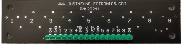
The Reflectance Sensor Array from Just4FunElectronics is an electronic component designed to detect the reflectance of a surface, which allows it to determine the presence and alignment of objects. This sensor is commonly used in line-following robots, edge detection, and surface monitoring applications.
Explore Projects Built with Reflectance Sensor Array 9 pin
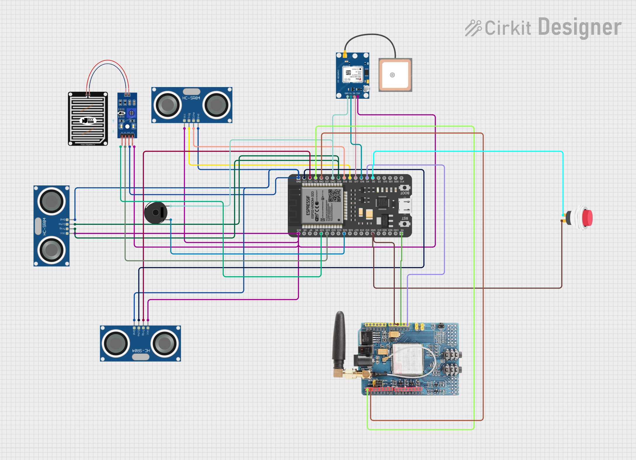
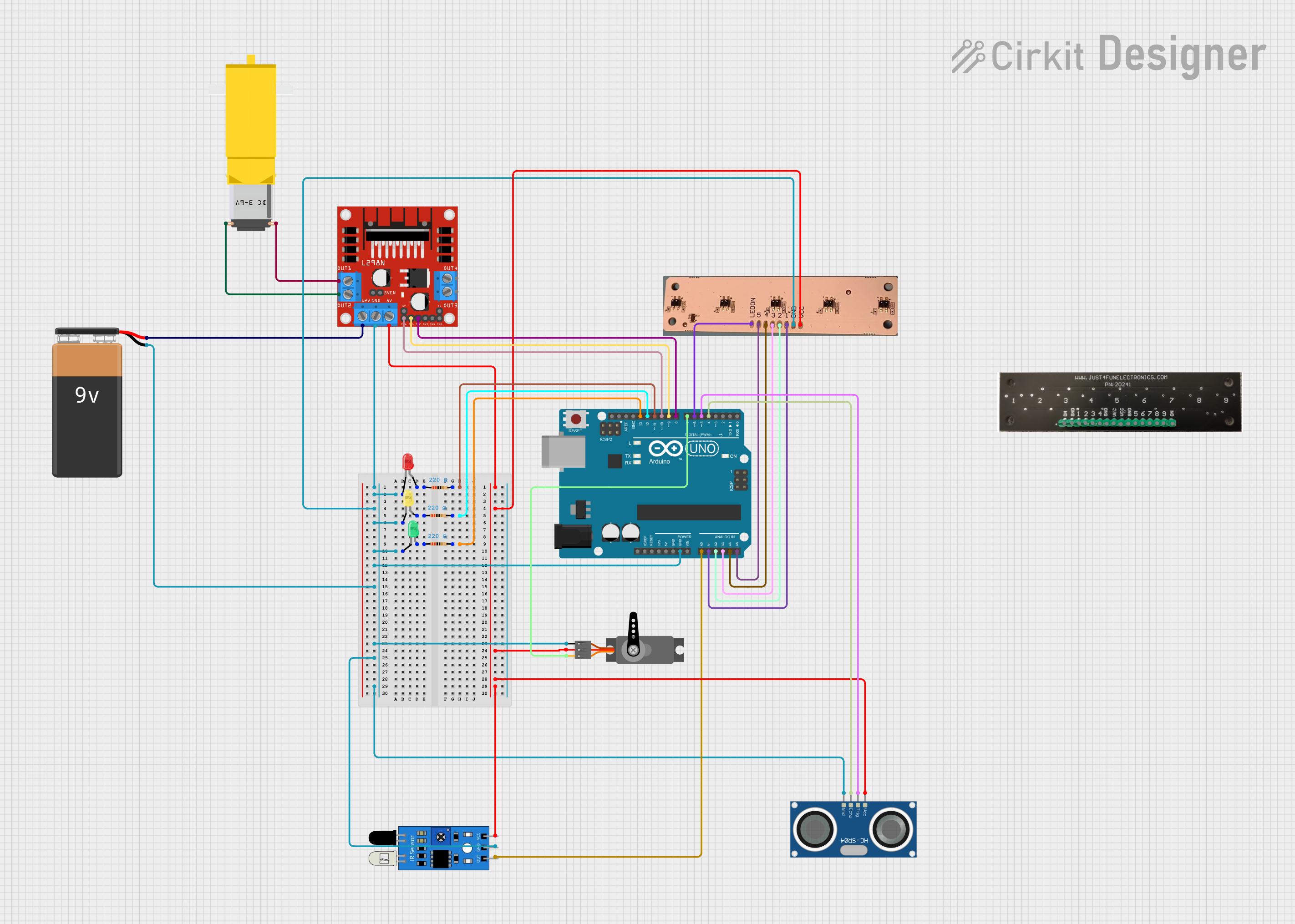
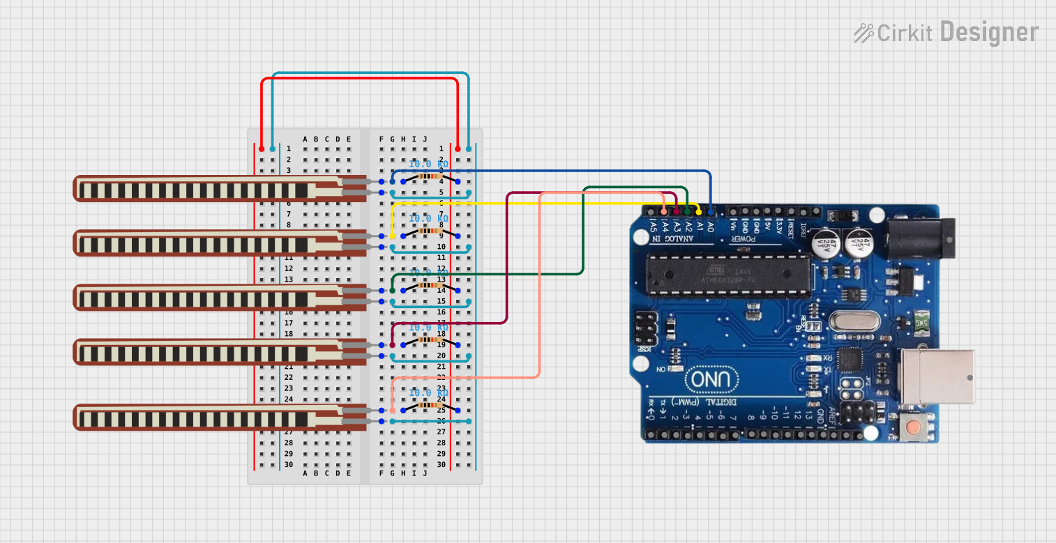
Explore Projects Built with Reflectance Sensor Array 9 pin
Common Applications
- Line-following robots
- Edge detection in conveyor systems
- Object alignment in manufacturing processes
- Surface reflectivity measurement
Technical Specifications
Key Technical Details
- Operating Voltage: 3.3V to 5V
- Current Consumption: 20mA (typical)
- Output Type: Digital I/O compatible
- Response Time: 5µs (typical)
- Ambient Light Rejection: Good
Pin Configuration and Descriptions
| Pin Number | Description | Notes |
|---|---|---|
| 1 | VCC | Connect to 3.3V or 5V power |
| 2 | GND | Ground |
| 3 | OUT1 | Digital output for sensor 1 |
| 4 | OUT2 | Digital output for sensor 2 |
| 5 | OUT3 | Digital output for sensor 3 |
| 6 | OUT4 | Digital output for sensor 4 |
| 7 | OUT5 | Digital output for sensor 5 |
| 8 | OUT6 | Digital output for sensor 6 |
| 9 | OUT7 | Digital output for sensor 7 |
Usage Instructions
How to Use the Component in a Circuit
- Connect the VCC pin to a 3.3V or 5V power supply.
- Connect the GND pin to the ground of your power supply.
- Connect OUT1 to OUT7 pins to the digital input pins on your microcontroller, such as an Arduino UNO.
- Place the sensor array close to the surface to detect its reflectance.
Important Considerations and Best Practices
- Ensure that the sensor array is mounted at a consistent height from the surface for accurate readings.
- Avoid exposing the sensor to direct sunlight or strong artificial light to prevent interference.
- Calibrate the sensor for the specific surface type and ambient light conditions for optimal performance.
Example Code for Arduino UNO
// Define sensor pins
const int sensorPins[] = {2, 3, 4, 5, 6, 7, 8}; // OUT1 to OUT7 connected to digital pins 2 to 8
const int numSensors = 7;

void setup() {
  // Initialize each sensor pin as an input
  for (int i = 0; i < numSensors; i++) {
    pinMode(sensorPins[i], INPUT);
  }
  Serial.begin(9600);
}

void loop() {
  // Read and print the value of each sensor
  for (int i = 0; i < numSensors; i++) {
    int sensorValue = digitalRead(sensorPins[i]);
    Serial.print("Sensor ");
    Serial.print(i + 1);
    Serial.print(": ");
    Serial.println(sensorValue);
  }
  delay(100); // Short delay before next reading
}
Troubleshooting and FAQs
Common Issues
- Inconsistent Readings: Ensure the sensor array is mounted at a consistent height and the surface is clean.
- No Readings: Check the power supply connections and ensure the pins are connected to the correct digital inputs on your microcontroller.
- Interference from Ambient Light: Calibrate the sensor to the current lighting conditions or shield the sensor from external light sources.
Solutions and Tips for Troubleshooting
- If the sensor is not responding, verify that all connections are secure and the microcontroller is powered on.
- Use serial output to debug and monitor sensor values in real-time.
- Adjust the height of the sensor array for optimal performance; typically, closer proximity to the surface yields better results.
FAQs
Q: Can the sensor array work with both 3.3V and 5V systems? A: Yes, the sensor array is compatible with both 3.3V and 5V power supplies.
Q: How can I improve the accuracy of the sensor? A: Ensure proper calibration, consistent sensor height, and minimal exposure to external light sources.
Q: Is it possible to use this sensor array outdoors? A: While the sensor has good ambient light rejection, it is best used in controlled lighting conditions for maximum reliability.