
How to Use AO3401: Examples, Pinouts, and Specs
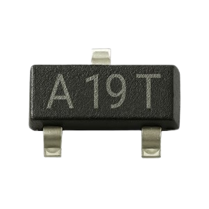
 Design with AO3401 in Cirkit Designer
Introduction
The AO3401 is an N-channel MOSFET (Metal-Oxide-Semiconductor Field-Effect Transistor) designed for low voltage and high-speed switching applications. It is widely used in power management, signal switching, and load control circuits due to its low on-resistance and fast switching capabilities. The AO3401 is particularly suitable for applications requiring efficient power delivery and minimal energy loss.
Explore Projects Built with AO3401
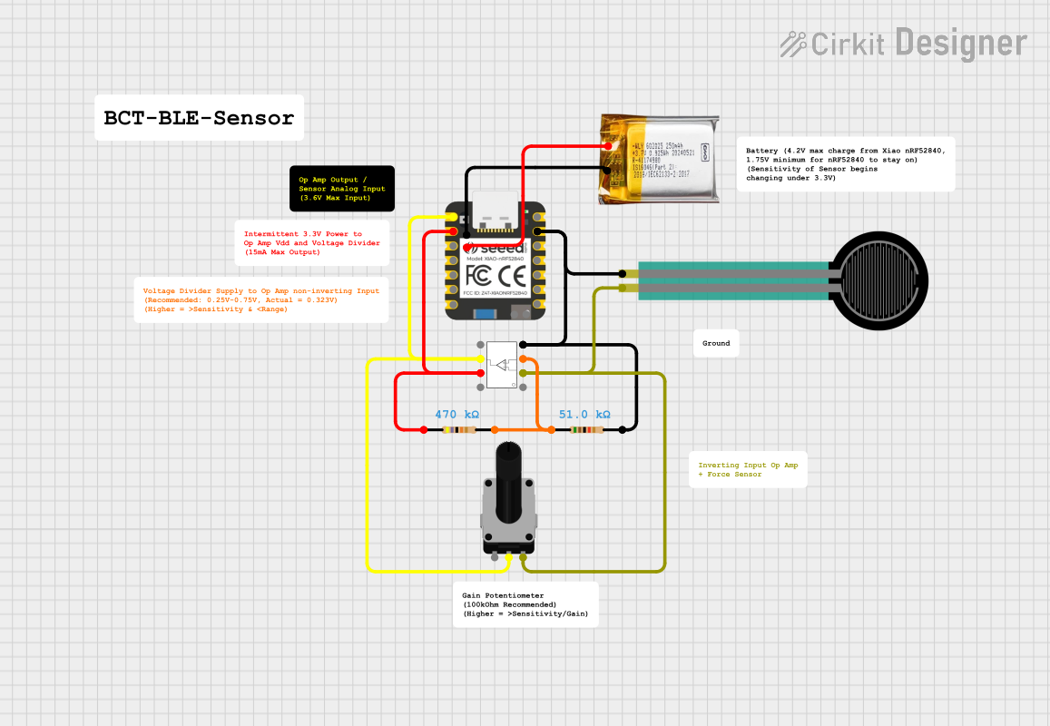 Open Project in Cirkit Designer
 Open Project in Cirkit Designer
 Open Project in Cirkit Designer
 Open Project in Cirkit Designer
Explore Projects Built with AO3401
Open Project in Cirkit DesignerOpen Project in Cirkit DesignerOpen Project in Cirkit DesignerOpen Project in Cirkit DesignerCommon Applications
- DC-DC converters
- Load switching in battery-powered devices
- Signal switching in microcontroller-based circuits
- Motor control and LED drivers
- General-purpose power management in consumer electronics
Technical Specifications
Key Specifications
| Parameter | Value |
|---|---|
| Type | N-Channel MOSFET |
| Maximum Drain-Source Voltage (VDS) | 30V |
| Maximum Gate-Source Voltage (VGS) | ±20V |
| Continuous Drain Current (ID) | 4.1A (at 25°C) |
| Pulsed Drain Current (IDM) | 20A |
| On-Resistance (RDS(on)) | 44mΩ (at VGS = 10V) |
| Gate Threshold Voltage (VGS(th)) | 1V to 3V |
| Power Dissipation (PD) | 1.4W |
| Operating Temperature Range | -55°C to +150°C |
| Package Type | SOT-23 |
Pin Configuration
The AO3401 is available in a 3-pin SOT-23 package. The pinout is as follows:
| Pin Number | Pin Name | Description |
|---|---|---|
| 1 | Gate | Controls the MOSFET switching |
| 2 | Source | Connected to the negative side of the circuit |
| 3 | Drain | Connected to the load or positive side of the circuit |
Usage Instructions
How to Use the AO3401 in a Circuit
- Power Supply Considerations: Ensure the supply voltage does not exceed the maximum drain-source voltage (30V) or gate-source voltage (±20V).
- Gate Drive: Use a gate voltage (VGS) between 4.5V and 10V for optimal performance. A lower gate voltage may result in higher on-resistance.
- Load Connection: Connect the load between the drain and the positive supply voltage. The source should be connected to the ground or negative terminal.
- Switching Control: Use a microcontroller, such as an Arduino, or a dedicated driver circuit to control the gate pin.
Example Circuit with Arduino UNO
Below is an example of how to use the AO3401 to control an LED with an Arduino UNO:
// Define the pin connected to the AO3401 Gate
const int mosfetGatePin = 9;

void setup() {
  pinMode(mosfetGatePin, OUTPUT); // Set the Gate pin as an output
}

void loop() {
  digitalWrite(mosfetGatePin, HIGH); // Turn on the MOSFET (LED ON)
  delay(1000);                       // Wait for 1 second
  digitalWrite(mosfetGatePin, LOW);  // Turn off the MOSFET (LED OFF)
  delay(1000);                       // Wait for 1 second
}
Important Considerations
- Heat Dissipation: Ensure proper heat dissipation, especially when operating at high currents. Use a heatsink or PCB thermal management techniques if necessary.
- Gate Resistor: Use a resistor (e.g., 10Ω to 100Ω) in series with the gate to limit inrush current and protect the microcontroller or driver circuit.
- Flyback Diode: When switching inductive loads (e.g., motors or relays), include a flyback diode across the load to protect the MOSFET from voltage spikes.
Troubleshooting and FAQs
Common Issues and Solutions
MOSFET Not Switching Properly
- Cause: Insufficient gate voltage.
- Solution: Ensure the gate voltage is within the recommended range (4.5V to 10V).
Excessive Heat Generation
- Cause: High current or inadequate heat dissipation.
- Solution: Check the load current and ensure proper thermal management.
MOSFET Always On or Off
- Cause: Incorrect wiring or damaged MOSFET.
- Solution: Verify the circuit connections and replace the MOSFET if necessary.
Microcontroller Resetting
- Cause: High inrush current through the gate.
- Solution: Add a gate resistor (10Ω to 100Ω) to limit the current.
FAQs
Q1: Can the AO3401 be used for high-frequency switching?
A1: Yes, the AO3401 is suitable for high-speed switching applications due to its low gate charge and fast switching characteristics.
Q2: What is the maximum load current the AO3401 can handle?
A2: The AO3401 can handle a continuous drain current of up to 4.1A at 25°C. Ensure proper heat dissipation for higher currents.
Q3: Can I use the AO3401 with a 3.3V microcontroller?
A3: While the AO3401 has a gate threshold voltage as low as 1V, it is recommended to use a gate voltage of at least 4.5V for optimal performance. Consider using a level shifter or a logic-level MOSFET for 3.3V systems.
Q4: Is the AO3401 suitable for switching inductive loads?
A4: Yes, but you must include a flyback diode across the load to protect the MOSFET from voltage spikes caused by the inductive load.